
You see questions on the 4×4 forums on a fairly frequent basis about hooking up fog lights, driving lights, etc. and everyone always says to use a power relay for them (which is absolutely correct). Look here for a typical circuit on hooking up some off-road lights on your Jeep.
Now….on those same 4×4 forums, one will also find questions about doing LED tail light conversions and what to use for backup lights. Many folks opt to use a pair of 55 watt driving lights for the backup lights. Not a bad idea at all since it really does give you some light behind the vehicle at night. However, some folks wire up the lights using the same wiring that fed those low power backup bulbs in the factory tail light housing and they use the backup switch in the transmission to control them. (VERY BAD IDEA!)
Simply put, if you need a 12V power relay and appropriate wiring to control the pair of 55 watt fog, driving, or off-road lights when they are mounted on the front of your Jeep, you need the same relay and wiring to control them when they are mounted on your rear bumper. If you don’t, you run a good chance of melting down your wiring harness, burning out your backup switch, or worse case, causing an electrical fire in your vehicle. All because you didn’t take the time to use a $4 relay and a couple dollars worth of wire to properly complete your backup light project.
Below are some posts from a JU thread. I did some cut and paste from the more than 100 posts in this thread….I didn’t think you wanted to read all 7 pages. The thread starter had some strange happenings going on with his TJ. A significant amount of time was expended while attempting to run the problem down. In the end, a bad wiring…. well, I’ll let you read the posts to get the rest of the story.
The thread starts with:
———-
2000 TJ. 35k original miles!
Drove the jeep at lunch and all was great. Started to leave later that day, and as I was backing up, I noticed that the engine wasn’t running right, I smelled something burning that smelled kind of electrical, but somehow different. The check engine light was on. Basically, it starts right up, but if you hit the throttle, it hesitates and then revs up. Seems sluggish then and runs a bit ragged too. If you rev it up and then get off the gas, RPM’s will drop pretty low or it will even die.
Plugged in a code reader and got the ‘ol P0123 code. (TPS voltage too high)
I installed a new TPS sensor, and it didn’t fix it. I’ve since read every post I could find about this, and have also replaced:
Both 02 sensors
Ignition switch
The other sensors on the throttle body
We’ve removed, cleaned & inspected the entire throttle body twice now. Traced the TPS wires back as far as possible- all looks OK. Eli pulled the TPS off of his jeep and installed it. Still no go. Put it back on his jeep and it works fine, so it’s not the TPS. We’ve tried to clear the code with the code reader, and by the procedure to clear out the adaptive memory.
I’m fast running out of ideas. Anyone else got any?
———-
I had a buddy of mine come over last night and trace this thing down. Turns out my computer is bad after all. It was showing the signal and voltage wires were shorting together. Then he tested it with the PCM unplugged, and it was gone. Testing the computer alone showed the short was in there.
It’s getting fixed under warranty on Friday. He said the emissions system is covered by an 8 year/80,000 mile warranty. I dunno if that’s true, or if he’s just getting it done for me, but I’m not complaining!
———-
I’m just ignorant when it comes to electronics. Gotta get my boys to help me out. Too bad you live in UT! I’d have a challenge for ya here!
I do have one question for ya. (We will be checking more grounds and doing what you suggested previously) I’m wondering- Is there ANY way this could be the clockspring? We haven’t replaced it. We have pulled the plugs off though, and the problem didn’t change. With everything hooked back up, my horn works, but my cruise will not turn on.
I also have my battery temp sensor out from under the battery. It’s hanging behind the battery. I can’t imagine that being a problem, but it does tie into the same mess according to the manual. (??)
Thanks!
———-
ok, been working on this thing all night !!! What I’ve got:
. p0123 code
. 5.15v on the reference circuit to the TPS and all other sensors
. 4.70v on the wire that should be reading the TPS position back to the computer (constant, no matter what the TPS position is, or if the TPS is plugged up or not)
. 0v on the ground wire for the TPS
With the volt meter displaying 5.15v at the TPS, we moved, shook, and wiggled every wire and plug in the engine compartment. Also unplugged each sensor, one at a time. Then we took apart the steering column and did the same with all the wires and connections. Then we looked at the service manual and found every chassis ground, took them off and cleaned them. The only thing we did that would change the 5.15v was turning on the turn signal or flashers. It would jump down to 5.08v and them back up again. We completely removed the switch and still had 5.15v though. While in the service manual we found a Ignition-Off Draw Test. You place a test light in between the ground post and negative battery cable. It should dimly light up, if it is bright, you have too much draw with the key off. We isolated each circuit by pulling fuses and relays, then unhooked the alternator per the test and still had a brightly lit bulb. The service manual didn’t cover what to do if all the tests failed.
Hell, I don’t know what to do next!
———-
Guys,
Have either of you done this:
You will find somewhere in the FSM a pin-out chart for the ECM. What that is, is a chart that will tell you what every single wire to the ECM is. With the key on and the problem occurring, check every single ground at the computer with it still plugged in. If you find the ground with the same voltage that the TPS is showing (4.7 V if I remember right) you will have found your problem. The other thing that could be happening is maybe the terminal itself in the computer connector is not connected to the wire (I have seen it repeatedly though rarely).
You check that by pulling all the connectors off turn the key off and disconnect the positive side of the battery. Measure the resistance on each ground pin (putting your multi-meter probe on the pin itself) and measure the resistance between the pin and battery ground. You should not have over 1 ohm (really less than that) but some multi-meters are not very accurate so just look for a ground that shows substantially more resistance than the other grounds.
———-
It’s fixed! It’s fixed!
WOOOOHHHOOOOO!!!!
Turns out that I had hooked up my aftermarket back-up lights into the regular circuit. I had read somewhere that it shouldn’t be too much draw.
It was. The purple & white wire melted for a long way and melted some other wires too. The fellas found it (initially) in the area behind the drivers dash speaker wires. What a mess.
We’ll be running some new wiring for the back-up lights, properly done with a relay & switch too.
BIG THANKS to Andy & Corby and ESPECIALLY to “my boy” Eli who was relentless in pursuing this thing to the end!
Thanks to all you guys who kept feeding us info on here too.
Lesson learned. DO NOT hook up your higher wattage back-up lights without the proper relays, etc!!!
———-
I am glad that’s over.
One thing that made this problem difficult was the way that it acted. EVERYTHING looked fine when measured with a multi-meter. Corby was able to get a DRB scan tool from the dealer and that’s when we started to zone in. The DRB showed that the PCM was seeing a condition that did not really exist. We started to suspect that we had a short feeding voltage back into the PCM. The FSM does not list what all the voltage ranges should be, so this became another intense search. The complete wiring harness under the hood was stripped and every wire checked. We then moved inside. Corby found what appeared to be a slightly melted wire in the main harness on the drivers side. Andy and I tore into it on Saturday to see what the problem was. (The dash in Dirks jeep cannot be removed because of the cage. This made for fun times) As we got the harness stripped back, I was amazed at the condition of the purple and white wire. It was burnt to a crisp. Since it was only one wire, we ruled out an external heat source and started looking for an over-current situation. BTW…. this wire was only completely visible when the complete bundle was pulled apart. It was in the middle. Since the FSM did not state what the wire was for, it had to be traced. Tracing it back to the fuse panel behind the glove box revealed more melting and a connection to position 7 (backup lights). This is a 10 amp circuit and there was a 30 amp fuse in it. Mystery solved.
I am pretty sure that the wire causing the PCM to fault was the cruise control switch wire. The wire always has voltage on it. (making it hard to find a problem) It just changes based on whether or not the switch was pressed. The BU light wire had melted into this wire in 3 places.
The IPF backup lights just plain had too much current draw for the circuit and that’s why a larger fuse was placed in the panel. I know most of us have done this or thought about doing this at some point when we keep blowing fuses. This one was a VERY hard lesson learned and will hopefully make others think twice before doing this. The Jeep could have easily caught on fire. Here is a picture of a length of wire I removed:
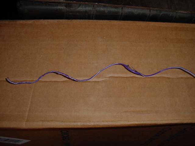
Learn from our mistakes and wire stuff right the first time. This seemingly harmless action cost a lot of money and over 80 hours of work.
Glad its finally fixed though!
———-
There you go folks….the shortened but true version of what can happen when you don’t spend a couple of extra $$ on a power relay and some appropriately sized wire. Simply put, it isn’t worth the hassle for a couple of dollars. The TJ owner was lucky the damage was not worse than it was. 80 hrs of trouble shooting a problem that was the result of a 30 minute shortcut. Do it right and use a relay when you wire in your heavy duty backup lights.