
Most of the time, you can get by with purchasing a CB antenna mount that has the coax and radio connector already attached to it. Every now and again, you can’t get the coax connector through a tight spot so you are forced to cut the connector off and then install a new one. Sometimes, the coax is damaged and you can salvage it but it may require a new connector installation before it is usable. Regardless of the reason, you can install a new RF connector if you have some basic soldering skills. There are probably much better write-ups on the web that cover this task, but I’ll include a short how-to here to go along with the other CB related topics. Here are some pics I snapped while installing an RF connector for a friend’s ham radio radio on his TJ.
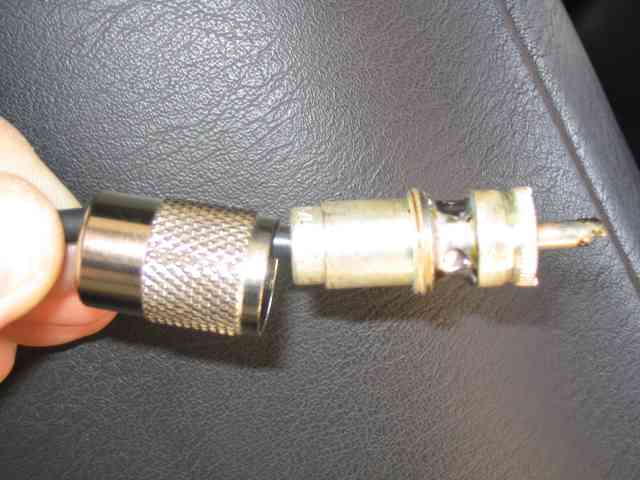
The above coaxial cable is type RG-58/U, a very common 50 ohm cable used for mobile antenna installation. The connector being installed is called a PL-259. The connector was originally made for a larger diameter coax. In order for it to fit the smaller RG-58/U coax, we use a reducer inside of the connector body. The will be threaded into the body of the connector once we get some other things taken care of.
First, CAREFULLY cut the outer black covering of the cable (around the diameter of the cable) and slide it off the cable. I say carefully because you do NOT want to cut the finely stranded wire braid that lies directly under the cable’s outer covering. A sharp knife will work for this and I cut off about 1 1/2″ of the outer covering. Once the covering is removed, Trim back the wire braid to about a length of 1/2″, as shown in the above picture. I use a small diagonal cutter to trim the braid back.
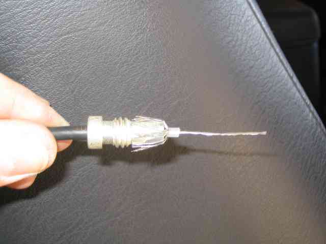
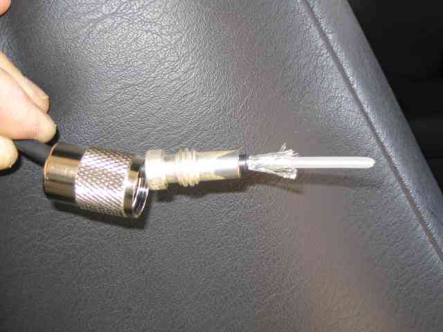
Slide the reducer forward until it is just even with the edge of the outer covering. Carefully fold the wire braid back onto the reducer. It is important that you get all of the wire braid folded back. If you leave just one strand sticking forward, it will most likely end up touching the center conductor wire when you assembly the connector and cause a short (which means you get to start all over). The wire braid should almost (but not quite) touch the threads on the reducer, as shown in the above picture. Using the same sharp knife, carefully trim the center conductor’s insulation (that would be the clear stuff that the wire brad was covering up) so that about a 1/16″ is sticking out past the end of the reducer, again, as seen in the above picture. Again, be very CAREFUL so as not to nick/cut the center conductor wire. Carefully pull the piece of cut insulation off of the center conductor.
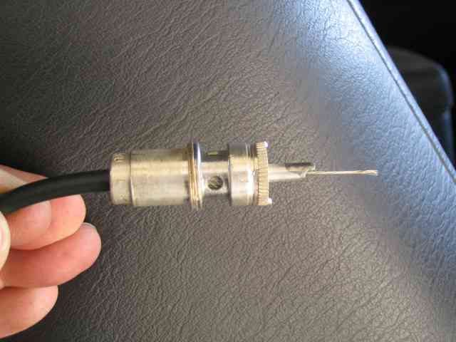
Take the body of the connector and carefully thread it onto the reducer. As you screw it on, you will see the end of the reducer (covered by the wire braid) appear in the holes as it the two pieces come together). The center conductor wire should protrude through the front of the connector as shown in the above picture. Hold the cable and reducer firmly and twist only the body of the connector as you join the two together. Once the body is fully threaded onto the reducer, carefully trim the center conductor so that it is flush with the end of the connector’s center pin. In other words, that piece of wire sticking out will be cut flush with the end of the tube it is going through.
Now, solder the center conductor to the center pin of the connector body. USE ROSIN CORE SOLDER!!!! (not acid core solder!) The solder should melt and flow smoothly. Do not apply so much heat that you melt the white Teflon insulator around the center pin. Let the connector cool for a minute or two. Now, solder the wire braid to the connector body through the small holes. There are usually 4 holes in the connector body and you should solder each of these. Again, you should see the solder melt and flow smoothly in and around the holes. Don’t get carried away with the heat as you will melt the outer coax covering inside the reducer. You will have the best results if you use a higher wattage soldering gun, about 150 watts worth. These are hot and big enough to quickly melt the solder to the connector without causing you to keep the soldering iron in contact so long that the cable insulation begins to melt. When done, clean the soldered area with some isopropyl alcohol as the last step.
Soldering RF connectors is an acquired talent. I’ll admit that I’ve messed a few up when I first tried it. If you don’t cut/knick the wires and you don’t melt the cable with the soldering iron, your connector will hopefully come out OK. If you get in a bind and all else fails, stop by your local CB shop and see if the folks there can help you out.