
Every now and then you end up doing a project just because you want to do it. It would be nice to have a widget or gadget on your Jeep, not because you need it, but rather just because you can. And hey, if it makes things easier while you are out wheelin’, so much the better. This is, in my opinion, one of those projects.
Since you are reading this on my web site, there’s a really good chance you are a TJ owner. And being a TJ owner, you know that the front end suspension of your lifted TJ has a tendency to unload when you are going up hill or trying to climb up an obstacle. The weight transfers towards the rear axle, the front end gets lighter, your springs extend, and you get less traction. If it is steep enough and the suspension unloads unexpectedly, you can find yourself going over backwards. OUCH!
There are times when compressing the front suspension can make the difference between flopping or making it over the obstacle. The infamous Currie Fire Ant was one of the first competition rigs (that I am aware of) to employ a method by which the front coil suspension could be compressed as needed to provide better handling in certain circumstances. While my rig is oh so far from being anything like the Fire Ant, I borrowed the compression idea to see if it could make a difference on my TJ when playing off-road. This write-up covers the major points of the project.
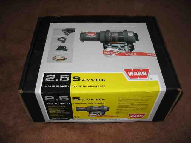
It all starts with the acquisition of Warn Industries new 2.5s ATV winch. The 2.5s is an updated version of the 2.5ci which is still available. The changes to the 2.5s include a mechanical brake and synthetic rope. A friend is doing this same project but with the 2.5ci. We’ll find out just how much difference, if any, exists between the two winches.
If you haven’t figured it out by now, the ATV winch is going to be the means by which the front suspension is compressed. Reel cable in, suspension sucks down to the bump stops. Release cable, suspension returns to normal ride height.
At this point, I need to make note of the phone conversation I had with Warn’s customer service department when this project was first starting. I called them to ask a couple of questions about the 2.5s, since it was listed as “NEW” on their web site and the local Warn dealer didn’t even have a part number for it. I explained to them what I was doing and was immediately informed that my application was not the intended use for the winch. They didn’t tell me that installing it in this fashion void the warrantee, but then again, I didn’t ask. I reminded him that lots of competition rigs that proudly display the big red “W” use these for just this purpose. (no response from customer service rep)
I ordered the winch from 4 Wheelers Supply here in Phoenix, Az. It was drop shipped to my house from Warn (via UPS) but I never received it. Either it was stolen or never delivered (another package from a different vendor was delivered that same day by UPS and it was not removed from my front porch). 4 Wheelers helped get things straightened out and I ended up driving down to their shop to pick up another (just like it) that they had ordered for stock.
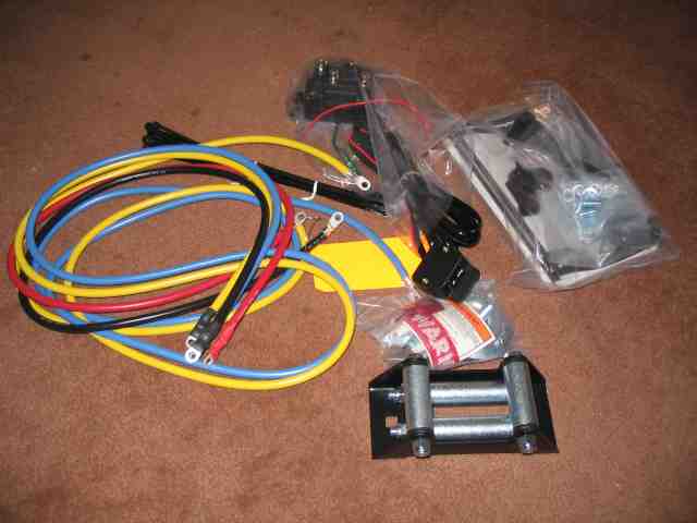
Just like the winch you have on your front bumper, this one comes with everything you need for the project except for the winch mounting plate. I ended up with a couple of parts that do not get used in the project, such as the roller fairlead and the winch hook. Unlike the 8K winch that may be on your front bumper, this one doesn’t have a big ugly relay control box. It has a fairly compact electrical actuator attaches to a small rocker switch that you use for controlling the winch. The power leads are all 6 gauge wiring.
With good suggestions from BobP and Troy, I spent part of a day working through some trial and error test fits in an attempt to come up with a workable mounting solution.
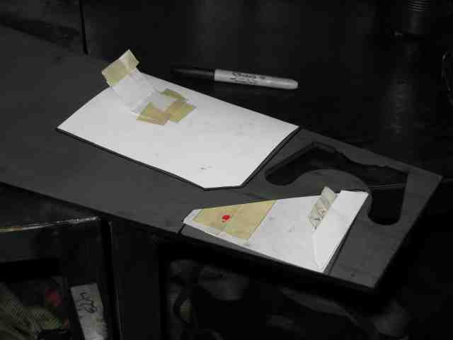
Once the cardboard templates had been finalized, I transferred the shapes to some 1/4″ steel and made a stop at the the band saw. A blending disc took off the sharp edges (to save my finger tips) and I punched the mounting holes for the winch body into the base plate.
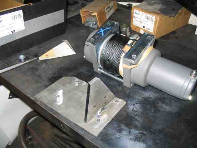
After more test fits with the winch both on and off of the base plate, the two pieces of the mounting plate were spot welded together. Right then, I realized that I should have taken the opportunity to punch the other mounting holes in the support plate. Oh well, not the first time an opportunity was missed. I grabbed a drill and made the remaining three holes.
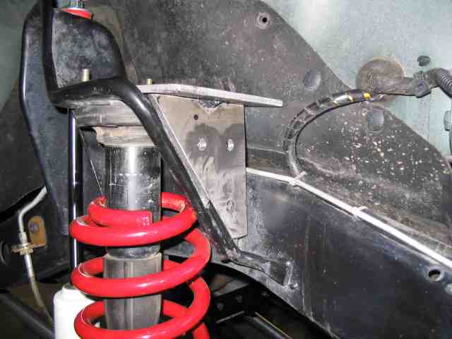
I was very pleased with the fit at this point. You can see the three holes in the support plate. I decided to not worry about the four bolt heads that anchor the winch to the mounting plate. At first, it looked like counter sinking was going to be required. After looking at it for a while, we determined that nothing would be gained by recessing the bolt heads. You can see a couple of the mounting bolts sticking out of the top of the plate. They had to be there to get the correct plate spacing off of the upper spring bucket when marking the holes in the support plate.
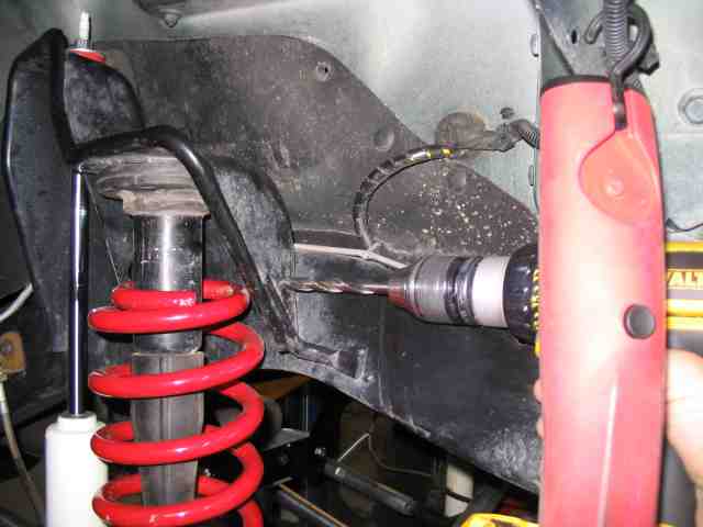
I marked the holes (on the support plate) with a transfer punch and then proceeded to drill them. To get the coil spring out of the way, I raised the TJ frame and let the suspension sag. It also makes it easier to get your fingers in there when it comes time to do the nuts and bolts later on, but it is not necessary.
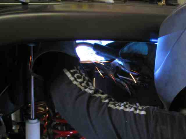
With the holes drilled in the support plate, Troy spot welded the last two pieces to the mounting plate. I went through a handful of ideas for attaching the other end of the mounting plate to the spring bucket.
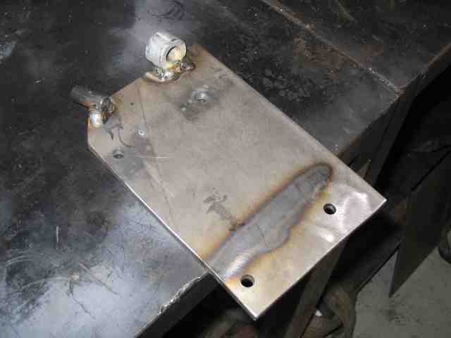
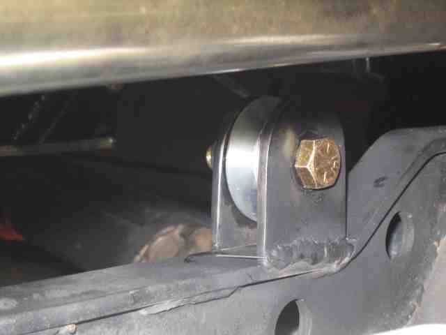
This is what was finally decided on as a workable solution. It consists of a locating pin and a collar. The locating pin slips into a hole drilled into the side of the shock tower. This anchors the corner of the mounting plate and prevents it from lifting up under torque. The collar will receive a bolt coming through the shock tower which will hold that corner of the mounting plate in place.
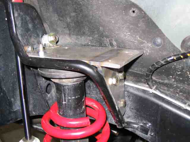
A picture of the mounting plate on top of the spring bucket. The hole for the locating pin was eyeballed and marked with the mounting plate bolted into position. I then removed the mounting plate and drilled the hole. I used the collar as a drill guide to make the hole in the shock tower. While all of the marking and drill was occurring, I made sure that the bolts in the support plate were all tight so I would have proper alignment.
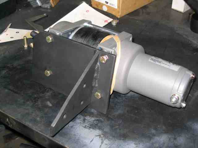
For about the 100th time, I attached the winch to the mounting plate using 1″ long 5/16″ grade 8 hardware.
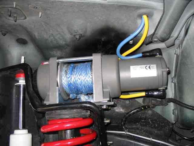
A view of the 2500 pound winch mounted in position. I discovered earlier that lifting the frame (to let the spring sag out of position) caused “things” to flex a small amount. While lifted, I had about 1/4″ clearance, at the closest point, between the winch body and the inner fender well. With the full weight of the vehicle back on the suspension, the winch body just touches the inner fender well. The easiest fix for this was appropriate pressure applied to the offending spot on the fender well. The most commonly available pressure source for something like this comes in the form of a big hammer. A few well place whacks took care of the clearance issue.
Suck-down Winch Project
With the winch mounted, it was time to make an attachment point for the axle. The plan was to run the winch line from the winch through the axle attachment point and then back up to the opposite frame rail where the winch line would be fastened.
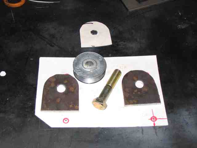
I cut another cardboard template and transferred it to some 3/16″ steel. Another session at the band saw and some touchup work with a flapper disc on the grinder yielded a couple of mounting tabs. A small pulley, made for a 1/2″ diameter electric motor shaft, was obtained at the local hardware store. A 1/2″ grade 8 bolt completes the pulley mount.
Since my D30 axle has a truss on it, it was decided to attach the pulley to the top of the truss to simplify the installation. It would have been preferred to attach it lower to the axle tube but since their was no clearance issues involved, the top of the truss was used. Some welding and a coat of black spray paint and it was ready to go.
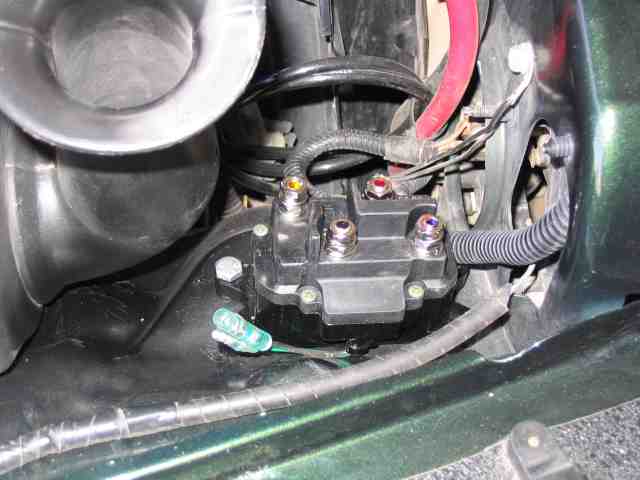
Warn calls the device that controls the winch the contactor. It serves the same purpose as the big relay box found on the Warn 8K winch. Luckily, it is much smaller since it doesn’t have to handle nearly as much current. I mounted mine on the passenger side of the engine compartment, just forward of the factory air cleaner. The base of the contactor is drilled for 1/4″ mounting hardware. One hole was already in the fender and I drilled a second hole. While there are four holes on the contactor, I didn’t see the need for using all of them. I used Nyloc nuts on the 1/4″ bolts to keep it secure.
The four terminals on the contactor are color coded; red, black, blue, and yellow. These correspond to the colors of the cables supplied by Warn.
The cables also have rubber boots that you slip onto the cables before connecting them to the winch and contactor. The instructions from Warn are very good (clear diagrams and good wording) so I won’t go into detail on hooking up the winch. If you are not color blind, you’ll be able to hook it up by matching the colored cables to the terminals.
No, I didn’t forget to put a grommet in the hole in the fender well that I passed the motor cables through. I didn’t have the correct size as I was doing the install and so I’ll pick it up at the hardware store tomorrow and slip it in.
NOTE: It is important to make certain that you do not allow the cables to rub on the edges of the sheet metal as this can cut into the insulation and case a very bad short when you energize the winch.
As you can see in the above photo, I obtained some larger diameter synthetic winch rope. In fact, this happens to be a piece of used Amsteel Blue that Barry (a local Jeeper) donated to the cause. Thanks Barry!
As I write this, I am not satisfied with the method I used to attach the Amsteel rope to the winch. Troy thought that the larger rope would work better. I’ll admit that it rides nicely in the pulley.
I just might switch back to the smaller winch rope that came with the winch. I’ll try a couple of things first and will add some comments to the write-up (at the end) once I figure out how I’m going to do it.
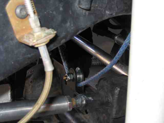
Here is a photo of the Amsteel Blue rope routed through the pulley to the tie off point on the opposite frame rail. To make an anchor point, we cut a link from a large piece of chain and welded the link to the frame.
Suck-down Winch Project
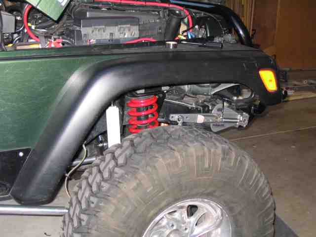
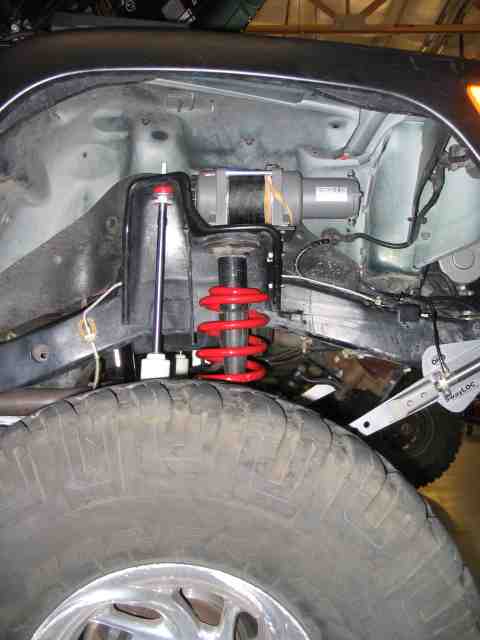
Here is a photo of the front suspension at normal ride height. Note the coil spring, position of the SwayLOC arm, and the distance between the fender flare and the tire.
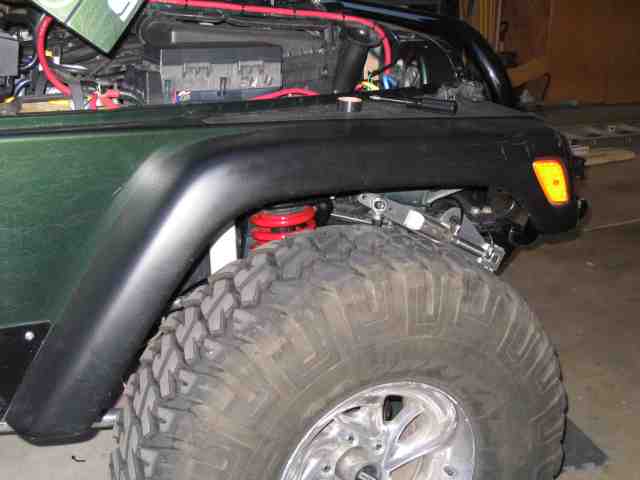
Here is a photo of the front suspension with the bump stops just hitting. Note the position of the SwayLOC arm and the distance between fender flare and tire. That is about 5~6″ of front spring compression. And yes, I checked for adequate clearance between the winch body and the SwayLOC arms at the start of this project.
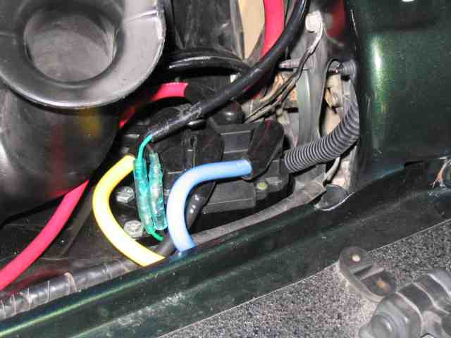
I realized I neglected to include a photo of the contactor with the battery and winch cables attached. The bluish/green bullet connectors provide the connection for the winch control switch in the cab. Warn provides slip on connector covers which are nice…..they protect against accidental contact of a dropped wrench causing the winch to engage (or your battery to short circuit).
How does it work?
I had a chance to test out the winch at the end of the week. I met with Russ and Kyle on Saturday AM to do a shakedown run for my upcoming trip to Moab. We warmed up on a trail to flex out the suspension (and check clearances on the new engine skid) and then moved on to a trail that started with a waterfall. A couple of years back, and locked TJ could drive the waterfall. Since then, some of the rock has chunked away and it now presents more of a challenge. I had been on it a couple of weeks ago and remembered the line I had used that gave me problems.
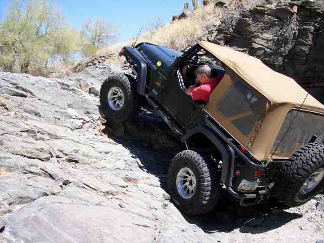
I started up the falls and sure enough, the right rear tire started dropping into a hole which caused the front end to unload and the driver’s side front tire to get air. I slowly walked the TJ up to the point where I had several feet of air under the tire and things were tippy….the TJ could easily be rocked from side to side. Russ was at the point of jumping onto the front bumper…..OK, a good time to try the suck down winch.
The winch control was mounted on my shifter….with a finger, I pressed the “IN” position and heard the winch engage. As it spooled in the Amsteel line, I watched the front end drop a bit, then a bit more, and with the weight now shifting towards the front of the vehicle, the tire settled onto the ground. With a bit more gas to the auto tranny, I let up on the brake a bit and walked up the falls as though I had no problems at all. I then repeated the same on the upper section of the waterfall, again, picking a line that would guarantee 3 wheel operation. As before, the front end settled down and I drove up the remaining section of the waterfall.
Russ and Kyle both watched…..they were impressed. At that point, Russ brought his 35″ TJ with lockers to the falls to work his way up. After more than 5 minutes of trying various lines, (yes, he was tippy on all of them), we strategically placed a couple of rocks and he made it up. Kyle’s attempt went better.
Once all three of us were at the top, Russ and Kyle agreed that it was time to install a suck down winch. I tried it again a bit later on another section of the trail and the results were again quite positive. It was able to shift the weight enough to the front axle to allow me to get over the obstacle. Granted, it is NOT the answer to every difficult obstacle, not by no means. It is, however, a darn good improvement to your rig, just like lockers and bigger tires.
I donated my templates to Troy since he was good enough to do the welding for me. He plans on making a kit available to those who wish to avoid the metal work needed to make their own.
I look forward to further testing of the winch’s performance during my week at Moab. See you there!