
There are all kinds of projects and modifications that we do to our Jeeps. Some involve tires and wheels, suspension lifts, axle upgrades…..the list goes on an on. One popular group mods fall in to the electrical category. Off-road lights, power inverters, wiring in a CB radio, adding a 12V on board air system, aux winch controller…..the list here goes on and on as well.
Some folks do electrical projects very well and some need all the help they can get. I want to think I fall somewhere in the middle. My electronics training in the Navy provided me with all the knowledge I need for the typical Jeep electrical project. I always ensure my connections are electrically reliable but I don’t always do a good job of cable routing and switch placement. I keep my cables away from wear points and hot spots but that doesn’t mean they are dressed off as they should be. While my electrical projects work well, they usually are not that great looking. On top of this, my 10 year old TJ as seen electrical mod on top of electrical mod during its lifetime…..and some of these are a little cluttered to say the least.
Then along comes the sPOD and now the Source from John at 4x4sPOD.com. If you are an electrical newbie, this two piece control unit and power center will put you on the road in minimal time and you’ll greatly reduce the possibility of trail failures and worse yet, electrical fires. If you are more like me, then you’ll feel right at home with these two units because the sPOD and Source are high quality assemblies that will simply your wiring projects and provide you with the reliability and functionality you demand.
Being active in several TJ on-line forums, I have read about the sPOD since it first hit the market. Every time you saw a thread about it, quality and customer service were two topics that were always in the discussion. I guess I should clarify a little….that would be high quality and excellent customer service. Now that I have one in front of me, I totally agree that the sheet metal work is nothing short of amazing, in my opinion. One of John’s specialties is precision sheet metal design and manufacturing. (yes, I’ve exchanged a few e-mail with him) Every piece of the sPOD I looked at confirmed this without question. The other half, the wiring, leaves nothing to be desired. Insulated terminals, abrasion guard on the cable assembly, waterproof connectors…..you don’t find these in Radio Shack (so don’t go looking for them). The sPOD and Source are made for the TJ owner who wants a professional/custom installation at an affordable price.
If you are just starting to build up your TJ, the sPOD and Source are an excellent investment right off the bat. You’ll be able to connect those various electrical projects very easily…..and you will keep the clutter to a minimum. If you are like me, with an accumulation of 10 years of electrical add-ons, the sPOD and Source are still an excellent investment. The term “Spring House Cleaning” comes to mind for me…..and that is exactly what I am doing. The sPOD and Source are going in to my TJ and a pile of relays, wiring, and switches are coming out. For me, it will greatly simplify the existing “wire harness thing” that has grown under the hood over the years. My legacy wiring projects (and Lady) will be getting a face lift, tummy tuck, liposuction, botox injections, boob job, and all that other stuff at the same time! How can I go wrong?
OK…..enough intro and background information….time to get this installation on the road. This write-up is being done in two parts. The first section covers the sPOD installation. The second section concludes with The Source install.
Note that this install was done in my ’98 TJ. Over the years, some of the TJ’s interior changed a bit. Newer TJs have plastic molding on the windshield frame. Please note that my installation will differ slightly from yours if you have a ’03 or newer TJ. The installation instructions that ship with your sPOD will provide the information you need for your TJ.
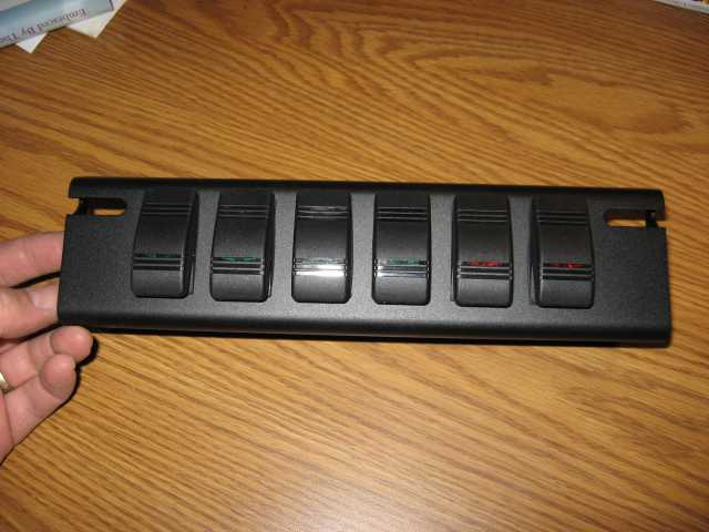
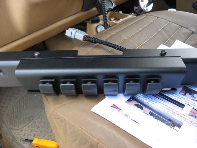
Meet sPOD. The heart of the sPOD is a switch panel that can be configured with a variety of switches and even a pressure gauge (for monitoring your on-board air system). The sPOD switch panel mounts into a header that is attached to the upper windshield frame on your TJ. The sPOD is available for TJs from ’97 through ’06. Early models (such as my ’98) require a relocation bracket (which is included) for the sun visors (more on that later).
The sPOD shown above has the newer Contura III rocker switches installed in it. At first glance, they are similar to the rocker switches supplied by ARB for controlling their air lockers. I really like them and am glad to see that John is offering them.
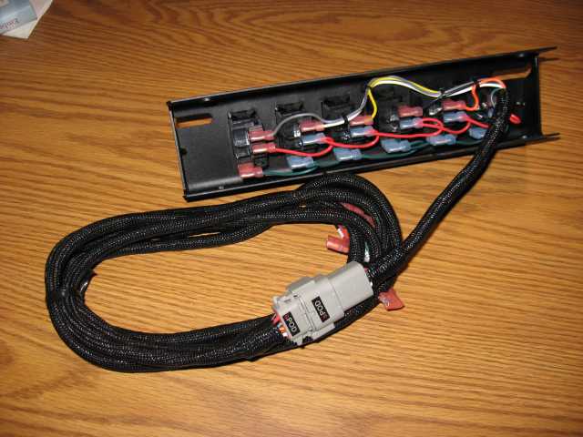
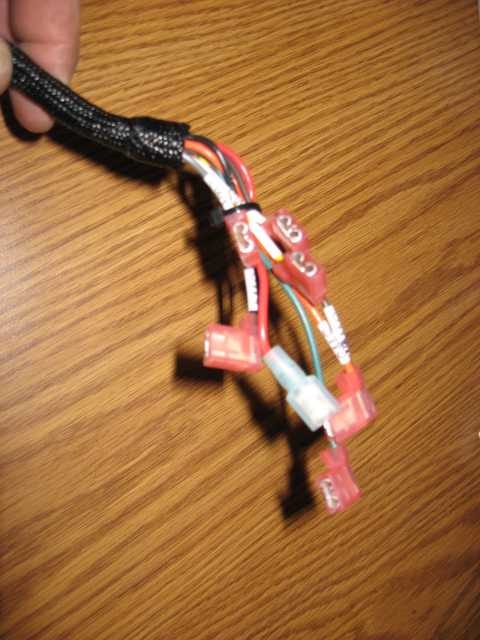
If you flip the sPOD switch panel over, you see a top notch wiring harness using right angle insulated terminal connectors. The wires are bundled into a pig-tail cable assembly that terminates in a waterproof multi-pin connector. This connector is then attached to a longer control cable which will find its way through a hole in the firewall and plug into the Source power center (under the hood).
Here is the engine compartment end of the control cable. The connector terminals that control each relay are labeled….nice attention to detail.
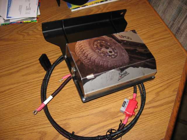
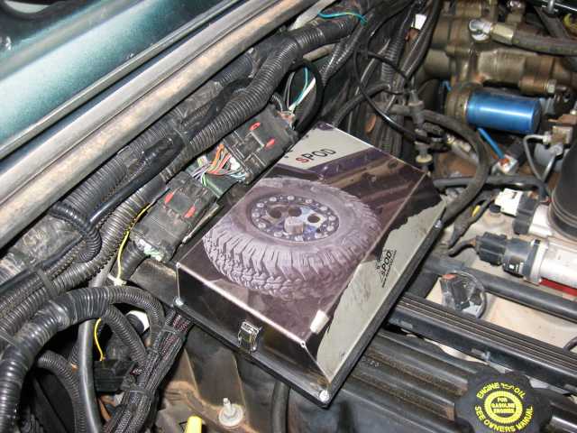
I can’t keep talking about the Source without at least showing you a photo of it. The Source power center mounts under the TJ’s hood. Under that totally cool anodized aluminum cover (I still haven’t figured out how John got that photo wrapped all around the cover) are 6 power relays, protection diodes, and fuses. There is a terminal strip for the control cable coming from the sPOD and there is an output terminal strip that provides you with a + and – power connection for each of the 6 circuits. The main power leads for the Source are protected by a resetting 50 amp circuit breaker and complete with heat shrink covered terminals for attaching to the battery. You’ll see much more of the Source when I get to that part of the installation.
Let me say here that John’s color printed installation instructions that shipped with the sPOD and Source are top notch. It was a genuine pleasure to use first generation documentation. (If more manufacturers shipped quality documentation instead of those 17th generation photocopies, it might put this web site out of business! LOL) The instructions are specific to your year vehicle so don’t worry about skipping non-applicable steps….they are all applicable.
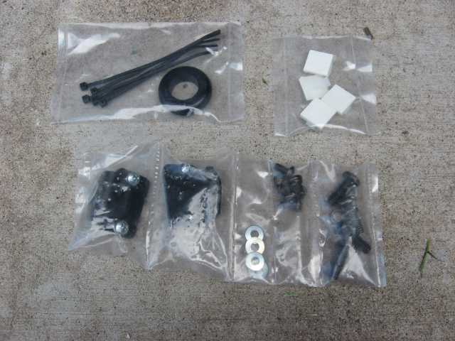
Mounting hardware and other needed items are provided in heavy plastic bags that are heat sealed to keep the contents where they belong. No sandwich baggies to split apart and spill their contents during shipping. (what, you haven’t gotten a kit where the parts are “bundled” in a Ziplock bag…..you MUST be a new to the aftermarket scene)
More sPOD
First step is to attach the sPOD switch panel to the header. Use four 10/32 Phillips head screws and lock washers from the hardware kit. Once assembled, find a spot to park the sPOD for 10 minutes while you clear some mounting real estate on the upper windshield frame.
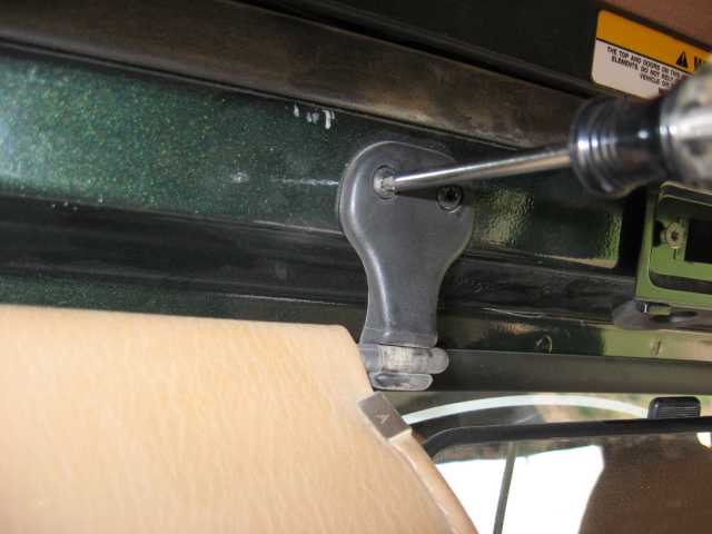
Remove both the driver’s and passenger’s sun visor and all associated mounting hardware. A Torx-20 screwdriver or bit will be required for this step.
Two Torx-20 screws attach the other end of the sun visor to the windshield frame. Remove these screws also. Do not discard any of the mounting hardware as you will re-use some of it later. As mentioned above, repeat this process on the passenger’s sun visor.
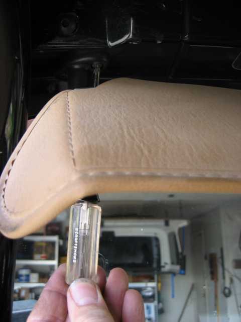
If you have the factory roll bar in your vehicle, you need to remove the inner Torx-40 bolt that attaches it to the windshield. Since I run a Toys by Troy sports bar, mine looks a little different than stock but none the less, I had a button head Allen bolt screwed into the windshield frame and so removed it.
With the two Torx-40 bolts removed from the windshield frame, grab the Torx-20 again and remove the two screws that hold the footman loop in place. Some loops are now riveted in place….you’ll have to drill out the rivet to remove the loop. In my case, my Icom 706 mounting plate long ago replaced the footman loop and used the same mounting holes. Hmmmmm…….time to find a new spot for the radio’s control head.
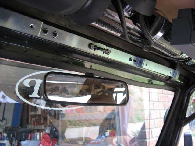
Next, grab the shinny mounting bracket that will be used to hold the previously assembled sPOD header in place. There are some small flat washers in the hardware kit….grab those too. Using the Torx-20 screws that you removed from the sun visors, slip a flat washer over the screw and loosely install four of them through the mounting bracket and into the windshield frame. Attach the footman loop at the center of the bracket using the original screws and mounting holes. Once you have the bracket lined up with the edge of the windshield frame, tighten the 6 screws that you installed.
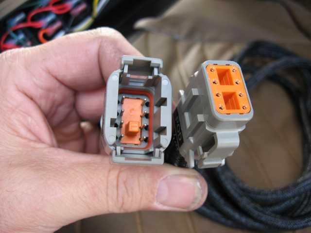
Locate the long control cable (the end with that cool waterproof connector on it). If you examine the plug on the control cable and the plug on the back of the sPOD, you will see that they can only fit together one way.
sPOD and The Source
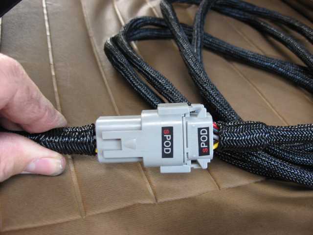
Carefully push the two plugs together until the locking tabs snap into position. OK…..time to get the sPOD and header mounted onto freshly installed mounting bracket (oh….I forgot to ask…..Have you noticed how difficult this is yet?)
From the hardware kit, remove four 1/4-20 screws and lock washers. Position the sPOD header over the mounting bracket and ensure the cable exits the header to the passenger side of the vehicle. Leave some slack in the cable (behind the header) so that if you have to remove the switch panel from the header, you will have some slack to work with.
Loosely thread the four screws through the header and into the mounting bracket. I used the bottom edge of the windshield frame and aligned the header to it while tightening the screws. Be careful not to over tighten the screws. The header should look nice and even with the windshield frame when you are done.
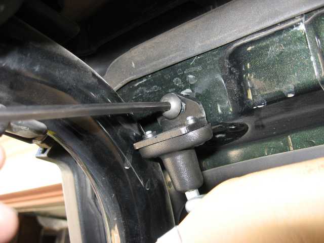
Next came the sun visor relocation bracket that John provides in the hardware kit. Using the two small screws supplied with the bracket, I screwed the visor mount onto the bracket as shown above. The bracket is then attached to the windshield frame using one of those Torx-40 screws your removed earlier. In my case, I had to remove a small amount of the plastic visor mount as it touched the sports bar a bit which through off the hole alignment. I removed about 1/8″ of plastic from the visor mount using a small hobby rasp….just about anything will work to produce adequate clearance. Don’t get carried away….clearance it a bit and then check the fit, repeating as necessary.
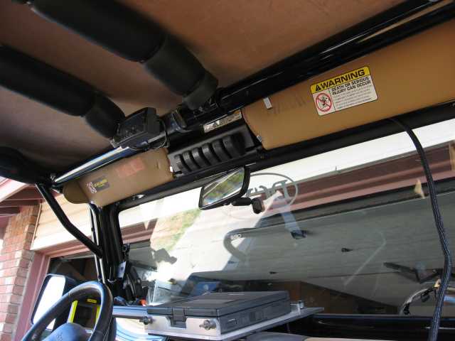
The other end of the sun visor is parked in a slot on the sPOD switch panel. Once I had that end of the sun visor in the slot, I tightened the Torx-40 screw to keep everything in place.
Repeat the same process on the passenger side sun visor. I had to clearance the visor bracket a small amount on this side too.
The sun visors now contact my TBT sports bar a small amount as I swing them up and down. It is not enough to cause any issues. Such things can happen when one starts applying multiple mods to the same area of the vehicle. Neither the sPOD nor the TBT sports bar are at fault as both of them allow unobstructed operation of the sun visors when the other is not present. I often tell people that there is no such thing as a bolt on mod…..TJs are not precision built (yes, there are significant variances in some dimensions) and when we wheel them hard enough, the body and frame will flex and tweak a bit, and these things can be expected. Hey…..you own a Jeep…..not a BMW. Grinding, drilling, sawsalling, welding, plasma cutting…..it’s all part of getting your Jeep just like you want it.
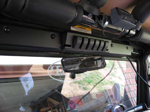
I haven’t routed the control cable down the passenger’s side of the windshield frame in this photo. I did want to show you what the sPOD looks like after the install is complete.
The sPOD install was painless and relatively quick. I say relatively quick because I use about double the time the average person would use (as I do on most of my installs) since I am always taking photos and making a few notes for later reference. If it’s a greasy kind of project (like servicing your Warn hubs), it takes me three times longer due to the frequent hand washing…..heah, I really don’t care to give my Canon digital a lube job.
sPOD and The Source
The control cable needs to get through the firewall in order to attach to the Source. A 1″ grommet is supplied to protect the cable from sharp edges. I rummaged around in my non-tool tool box (that would be the one that doesn’t have wrenches, sockets, ratchets, etc. in it) and found a few hole saws. Two of them were for 1″ holes and one of those hadn’t even been used yet.
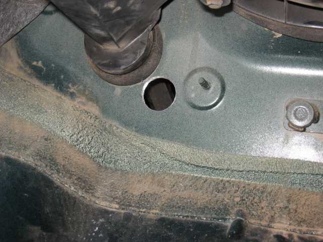
This is one of those steps where I wanted to make sure I was putting the hole in the correct location the first time. Measure twice…..heck, measure a dozen times and drill just once! With the carpet pulled back from the passenger side floor board area, I decided on the spot for the hole. I checked for adequate clearance on the engine side as I didn’t want to drill through and into a blind spot or something on the other side. My spot looked clear so I chucked up the 1″ hole saw and went at it. About 10 seconds later, I had a nice clean hole right where I wanted it.
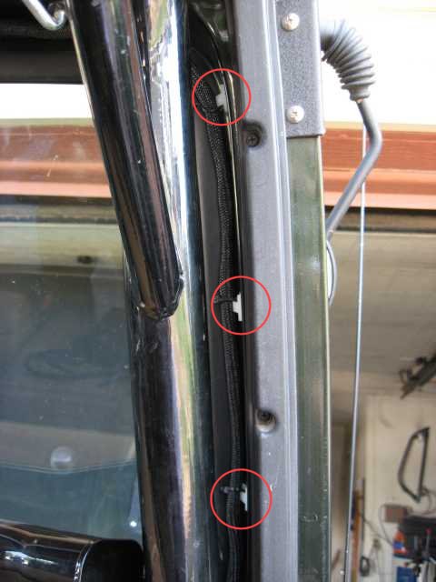
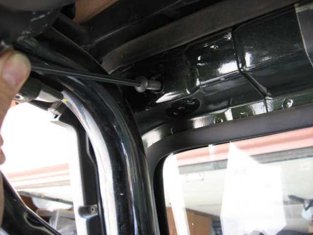
Small cable ties are supplied, along with self adhesive mounting pads, for securing the control cable. I wiped down the area with some isopropyl alcohol I keep in the garage for such things. You won’t get good adhesion on a dusty/oily surface. I put three of the pads along the windshield frame adjacent to the rubber molding that holds the windshield in place (see red circled areas). I put the remaining pad at the top of the windshield near the area where the control cable exits sPOD.
It took a minute or two to snake the cable down through the corner of the dash and out along the right side of the glove box. This keeps it out of site and well protected and puts it into a good position to go through the firewall hole.
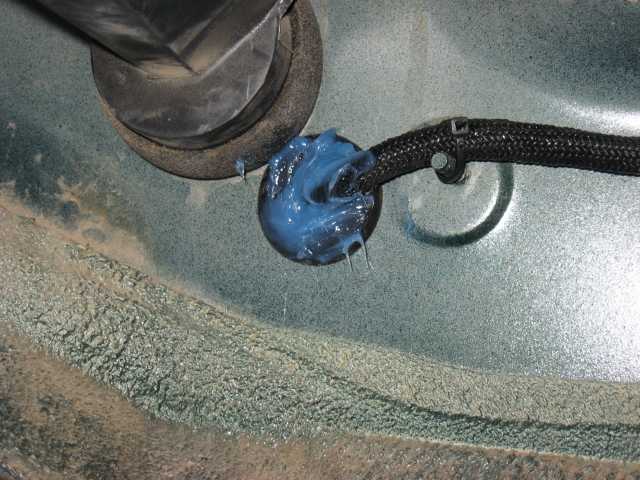
With the control cable routed through the grommet lined hole, I decided there was just a little too much of an air gap in the grommet. Some blue (any color will work) RTV was sitting on the shelf and a few squirts of it did a nice job of filling up the hole. Should I ever need to remove the cable, the RTV can be easily removed.
The sPOD is pretty much installed now except for hooking up the cable which is now on the other side of the firewall.
sPOD and The Source
Here is a before photo of the relay bank that is mounted on the underside of my hood. This will all be going away (yes!) when The Source is installed. I’ll be spending some time on cleaning up some of the other wiring as well. Yes, I know it needs work.
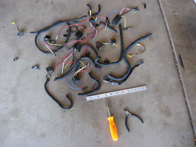
After a couple of hours under the hood, this was the first pile of pieces and parts that were removed. Five relays, five relay sockets, and some misc wiring and wire loom make up the bulk of it. The relay grounds and power leads were all removed. I cut some self adhesive labels and marked the +12V feeds to the various items (rock lights, radio, power inverter, etc.) as these will be connected to The Source when I get to that part of the install. I didn’t want to lose track of which one did what as it would take extra time later on to sort it all out.
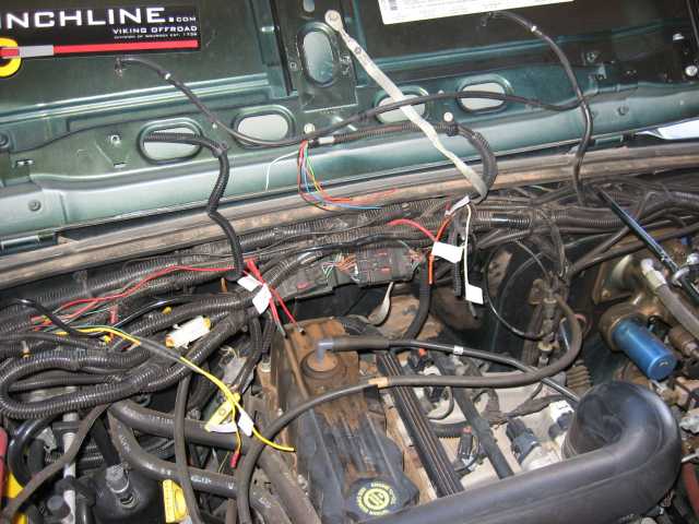
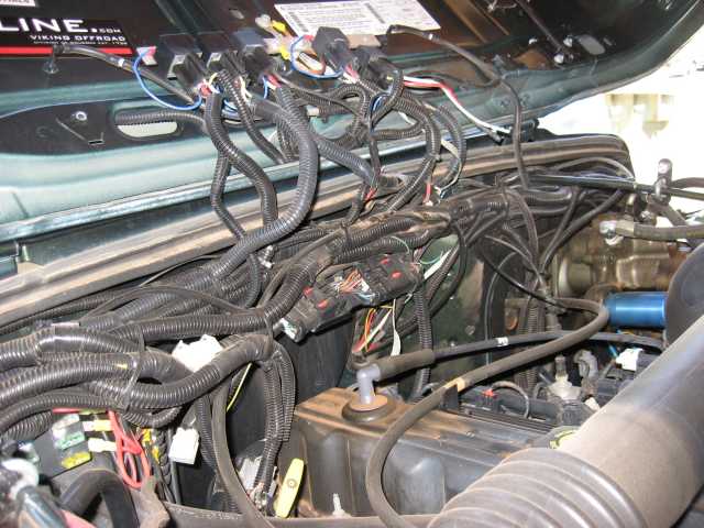
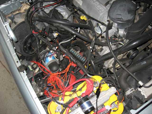
Here is a look at the engine compartment after the components and wiring in the previous photo were removed. Still some to go but I’m making progress. You can see the various wires with the white labels indicating their function.
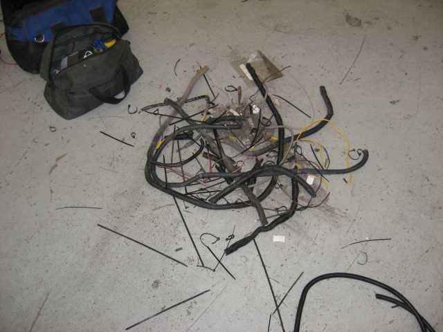
This was pile #3 from pulling wiring from the engine compartment. I forgot to take a snapshot of pile #2 which was on the garage floor yesterday afternoon. It looked pretty much like this one. I must admit that after all these years, the engine compartment had acquired quite a bit of wiring. I pulled all the old wiring for the rock lights and the fogs. Why? One of the two fog lights was bad (it was a cheap pair of lights) and the same was true of the rock lights. I don’t do night runs much any more and so the rock lights may or may not be installed again. I do want to install a new set of lights up front.
I removed the two bolts in the firewall (directly behind the valve cover) and attached The Source’s mounting bracket. Note that both of these bolts have ground wires attached to them so be sure they remain in place when you attach the bracket.
With the bracket in place, the control cable from the sPOD was attached to the input terminals. These are the six switch wires that are used to turn the power relays on and off. Along with the six control wires, there is also a fused positive lead and a ground wire that completes the control circuit cabling. These are used to supply power to the sPOD switches.
One circuit at a time, I routed the wires to The Source and connected them. I soldered ring terminals onto the wires and insulated each one with heat shrink tubing. The wires were then attached to the appropriate output and ground terminals for each circuit. In a couple of cases, the circuit ground was already connected at a different location so I used only the +12V output terminal for those circuits.
sPOD and The Source
With some more work on the wiring looms, I was able to combine a number of runs together while several others were removed or rerouted. At this point in time, I have 4 circuits wired. These include:
ARB compressor
CB and ham radios
Aux tranny cooler fan
110VAC power inverter
The remaining two circuits have a couple of possibilities as to what they will receive. As I mentioned, I removed the fog lamps and so believe a set of off-road lights will be put in their place. One circuit will be used for that. I think I might use the remaining circuit to control my ExtremeAire OBA system. The jury is still out on that one…..not sure quite yet.
With the output circuits now connected to the terminals, it was time to get some power to The Source. There are three power cables that must be attached. Two are connected to +12V and one to ground. Why two to +12V? One of them is the main power feed for The Source. The other is a smaller gauge cable with an in-line fuse that provides power for the control circuits and sPOD.
I had checked my connections twice (well, maybe 4 or 5 times in some cases) and felt confident that my fire extinguisher that was sitting on the bench should be able to quench the flames of most any electrical fire. (hey, I’m just kidding) I hopped into the driver’s seat and reached up and flipped the switch for circuit #1. Since I didn’t have anything attached to this, I figured it would be a good test. Hey, the switch illuminated…and a quick check in the engine compartment indicated no smoke either! I was off to a great start for sure!
With an empty circuit fully energized (can you do that?), I flipped the switch for #3. The ARB compressor came to life and my SwayLOC actuator unlocked itself (yes, I leave the SwayLOC switch turned on so it goes into off-road mode as soon as the compressor pumps up). OK, circuit #3 was working just fine. I turned off the compressor and tried the remaining circuits. Radios checked out OK, tranny fan indicator lit, and the power inverter’s red power light glowed softly. SUCCESS!
I’ve managed to do some of the work on my TJ at Troy’s shop on my day off (Toys by Troy). A number of customers circulate through the shop on any given day and I’ve had the chance to show several of them the sPOD and Source. All have been quite taken with it.
Troy met John (Mr. sPOD) at this year’s Easter Jeep Safari. Troy had seen my sPOD and Source before EJS and so when he saw John, he was able to get a Source for a customer’s Bronco. Troy knew I would do the wiring on the Bronco if he asked me so he did. I snapped a few photos of the before and after to include in this write-up. As you will see, you can use the Source on more than just TJs.
The Bronco’s wiring was put together during a short afternoon session so that the vehicle could make it to an off-road run that had to be attended. Orange wire was the color of the day.
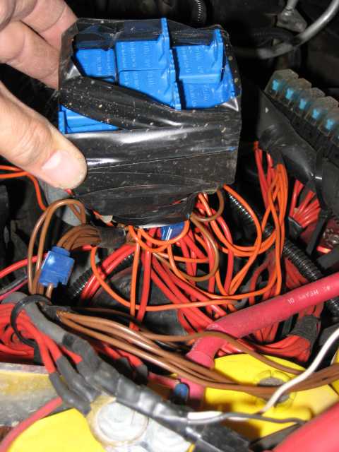
Here is the cluster of power relays. A couple of yards of electrical tape were used to bundle them together. No sockets were used and there was a LOT of un-insulated terminal lugs on the bottom of the relays.
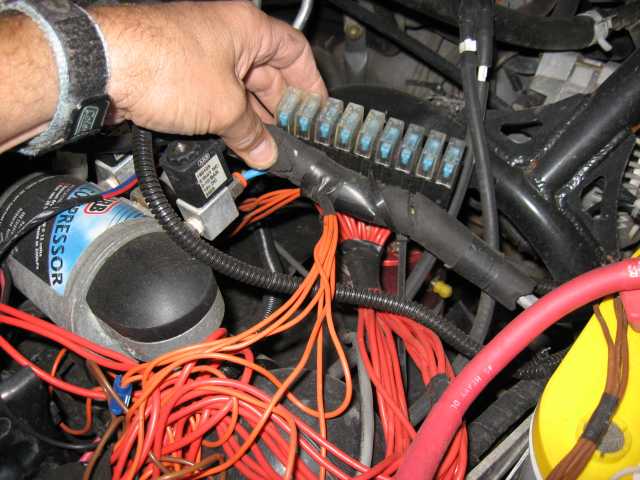
Here was the bank of fuse holders used to protect the various relayed circuits. Some electrical tape was used to hold them in place.
So all of this “stuff” was removed from the Bronco by me (hey, since I didn’t put it in, I didn’t feel bad about taking it out!) on one of my Monday trips to the shop. I was hoping that someone else might finish it but all of the guys were really nice and left it all for me to finish. (nice, eah?)
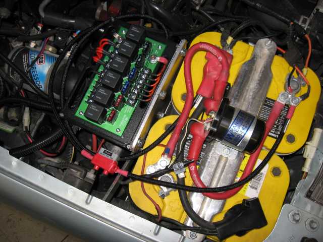
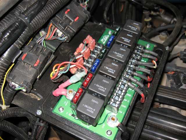
Here is the final configuration less a couple of circuits that I wired during the next visit to Troy’s. One of the fab techs made a nice aluminum mounting bracket that bolted to the fender well. We attached the Source to the bracket and it fit like a glove. I used solder on terminals with heat shrink for insulation. The Bronco had a custom switch center in it which performed the same function as the sPOD. It all came out very nicely and I know the customer was pretty happy with the results, even if the Source cover has a Jeep on it!
If you get a chance to put one of these in your vehicle, don’t pass it up. It works nicely and gives you an easily managed power distribution center. I’m looking forward to many years of use from mine.
Good trails to you and remember to TREADLightly!