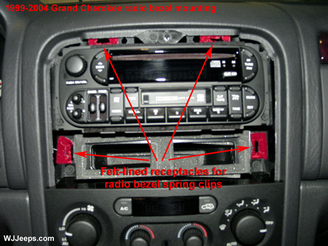
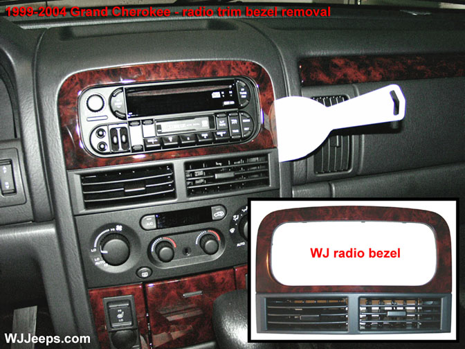
- The radio/vent trim bezel is held in place with 4 spring clips. With a wide flat tool (a 3″ plastic spackle tool works great), gently pry on each vertical side and carefully pull the bezel out a little at a time until it is free. The red areas in the center picture are the felt-lined receptacles that the bezel spring clips fit in to, which shows the general area of where to pry when removing the bezel.
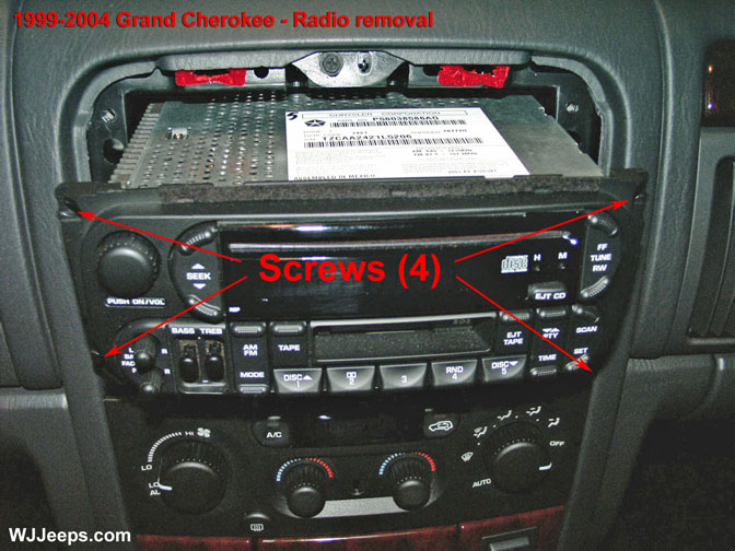
- The radio is secured with four phillips screws, one in each corner.
- Slide the radio straight out and remove the wiring harnesse(s), antenna connector, and CD changer connector (if equipped). 1999-2001 models may have an additional single wire connector for the PCI connection and also a ground wire connection. Note that on the new 2002 and up models the antenna is locked onto its connector on the back of the radio. The outside collar of the antenna connector must be slid back in order to release the cable.
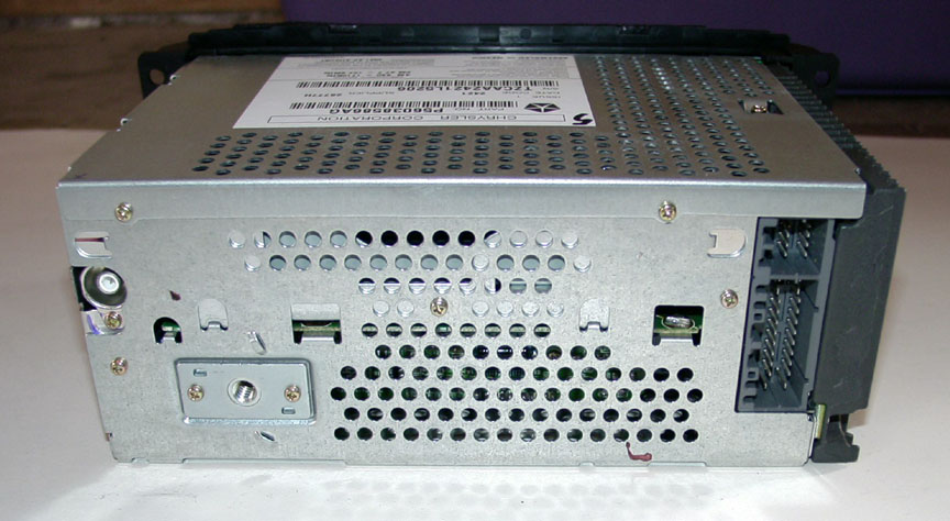
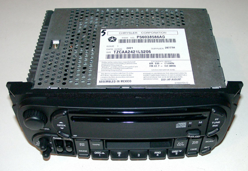
AM/FM/Cassette/CD Radio featuring the new 22-pin connector (12-pin socket plus a 10-pin socket) and a new style locking antenna connector. The change was made starting with the 2002 model year, replacing the older style dual 7-pin connectors. With a special wiring harness, the 2002 and later model radios can be adapted to fit 1999-2001 WJ’s.
Infinity GoldTM amplifier
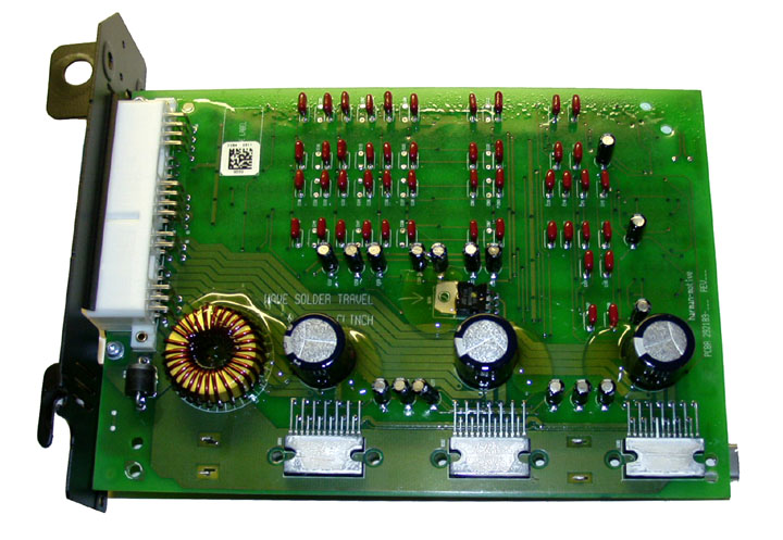
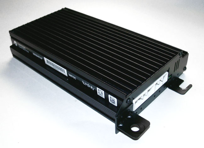
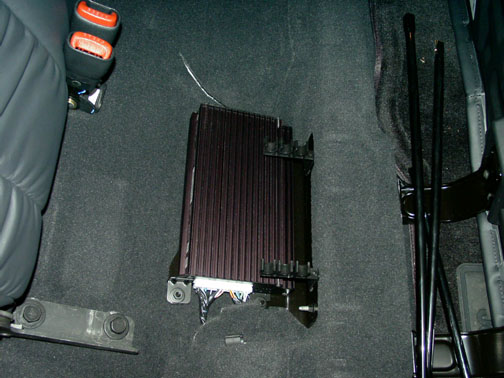
- Located under the rear passenger-side seat, removal of the Infinity amplifier is pretty much self-explanatory. Four nuts to remove, and two wire harnesses to unplug. The photo at far right shows the simple circuit board of the Amp, the only component inside the unit.
Dash speakers
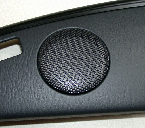
2.5″ tweeters
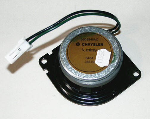
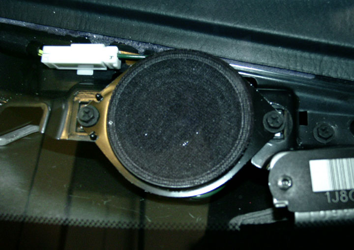
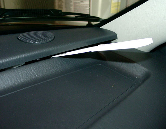
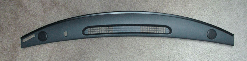
The dash tweeters are located under the top instrument panel cover
- With a wide flat tool (3″ plastic putty knife or similar, as shown in upper left photo), gently pry the dash trim panel upwards starting at either end. You can then get your fingers under the lip and lift it up, working your way to the opposite end. The trim is held in place by four spring clips. There are no parts or wires attached to the trim cover.
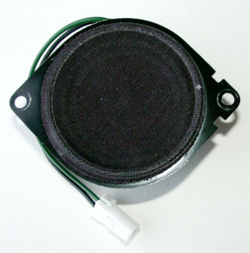
- The tweeters are held in place by two #2 phillips screws with 7mm hex heads. A 7mm open end wrench works best, or you can use a very short or right-angled screwdriver.
Tweeter mounting specifications:
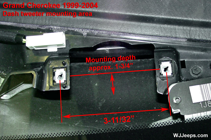
- Speaker opening: 3-3/4″ x 2-3/4+”
- Speaker opening depth: 1-3/4″
- Factory speaker thickness: 1-3/8″
- Factory speaker diameter: 2-1/2″
- Distance between screws: 3-11/32″
- Factory speaker part #: 56038411AC
Front door speakers

Door panel removal:
- Remove the 3 door panel screws (above left, first photo):1. Phillips head, located inside the pull-handle pocket tray.2. Torx screw, located behind the chrome door handle. This is also referred to as a “nutsert” and requires a Torx T-25 bit. The opening to access the screw is very small so a screwdriver-style T-25 works best.3. Phillips head screw, located on the upper right top area (by the mirror bezel). It is covered by a round plastic trim plug that needs to be popped out (a small flat screwdriver works best for this).
- Using a trim removal tool (Miller tool # C-4829 or similar), detach each of the 10 plastic trim panel fasteners. Lift door panel upward and out to separate it from the door. The easiest way I have found is to use a plastic putty knife or similar tool to pry one of the bottom lower fasteners loose. Once that is done you can reach underneath with your fingers and pull the door trim off by hand, slowly working around the edges to pop the rest of the fasteners loose as you go along.
- While holding the loose trim panel in place, remove both of the metal actuator rods. They are secured with yellow snap-on plastic retainer clips that need to be pried away from the side of the metal rod. Lift the rods straight up and out of their sockets.
- Unhook the wiring connectors. One for the mirror, and the large white main connector (for power locks/windows). Vehicles with the day/night mirrors will have an additional 2-pin harness on the drivers side to unplug. The connector ends have a tab on one side that needs to be pushed in to disengage them.
- The 6″x9″ speaker is attached with 4 phillips screws. Remove and then disconnect the speaker wire harness.
Front speaker mounting specifications:
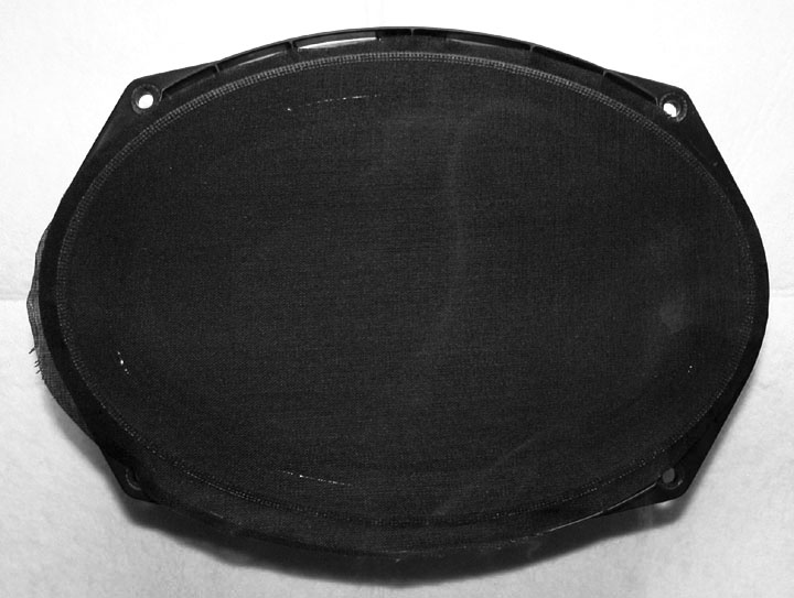
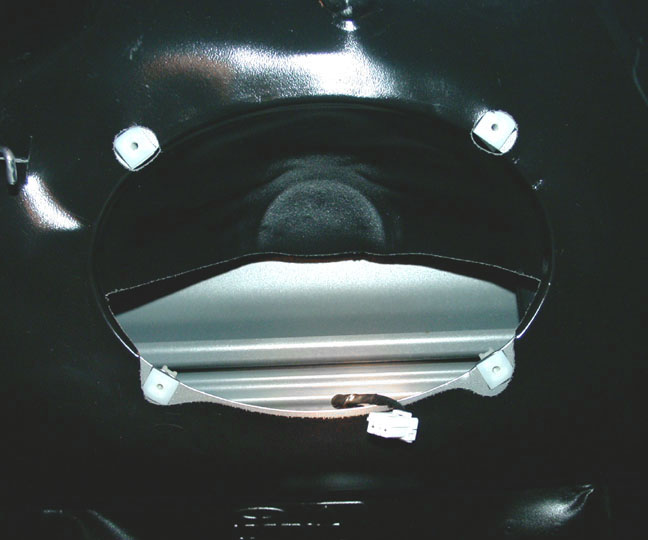
- Speaker cut-out opening: 8-1/2″ x 5-3/4″
- Speaker opening depth (to glass): 2-7/8″
- Factory speaker mounting depth: 2-11/16″
- Factory speaker thickness: 3-5/16″
- Factory speaker size: 9-1/8″ x 6-5/16″
- Distance between screws: 6-9/16″ & 4-5/8″
- Factory speaker part # (Infinity): 56038656AA
Rear door speakers
Door panel removal:
- Remove the 2 door panel screws (above left, first photo):1. Phillips head, located inside the pull-handle pocket tray.2. Torx screw, located behind the chrome door handle. This is also referred to as a “nutsert” and requires a Torx T-25 bit. The opening to access the screw is very small so a screwdriver-style T-25 works best.
- Using a trim removal tool (part # C-4829 or similar), detach the 10 plastic trim panel fasteners. Lift door panel upward and out to separate it from the door. You can also use a plastic putty knife or similar tool to pry one of the lower fasteners loose. Once that is done you can pull the door trim off by hand, slowly working around the edge to pop the rest of the fasteners loose as you go along.
- While holding the loose trim panel in place, remove both of the metal actuator rods. They are secured with yellow snap-on plastic retainer clips that need to be pried away from the side of the metal rod. Lift the rods straight up and out of their sockets.
- Unhook the wiring connectors. One for mirror (if electric), and the large white main connector (for power locks/windows). These will have a tab on one side that needs to be pushed in while pulling the plug out.
- The speaker is attached with 3 phillips screws. Remove and then disconnect the speaker wire hold clip and harness.
Rear speaker mounting specifications:
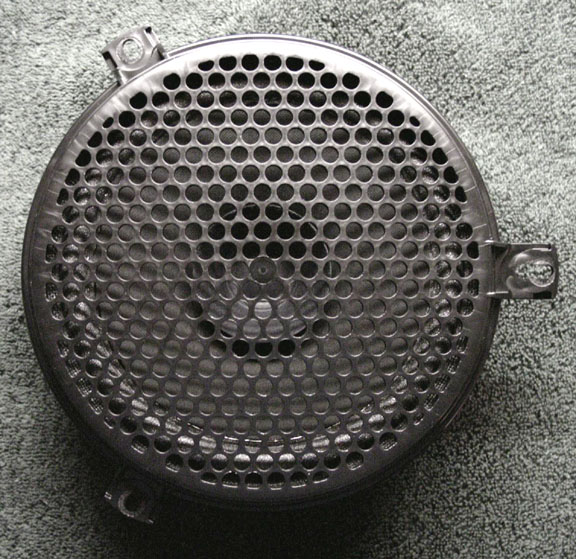
- Speaker cut-out opening: 5-3/4″ diameter
- Speaker opening depth (to glass): 2-7/8″
- Factory speaker mounting depth: 1-7/8″
- Factory speaker thickness: 2-9/16″
- Factory speaker size w/grill: 6-3/4″
- Distance between screws: 6-1/2″
- Factory speaker part # (Infinity): 56038657AA
10-Disc CD changer
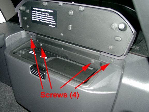
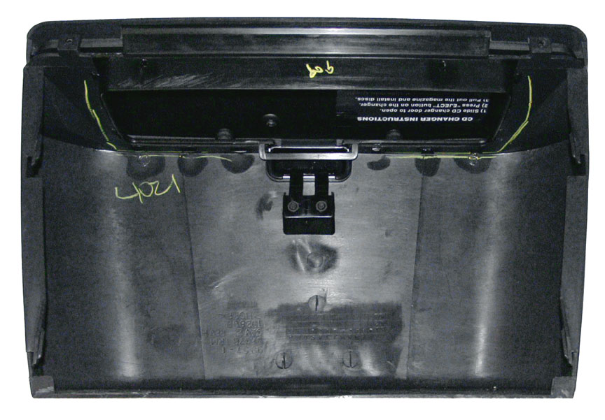
- Open lid and remove 4 the phillips head screws that run along the top edge of the compartment hinge. Lift compartment housing straight up an inch or so until it stops and then pull straight out to remove.
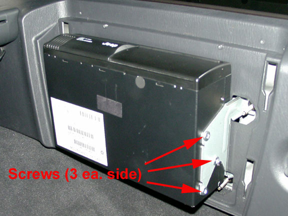
- Remove 6 phillips screws that attach changer to bracket, 3 on each side. A very short or angled screwdriver is needed for one screw on each side. Unhook wire connector on left side. The unit can now be slid out away from the bracket.
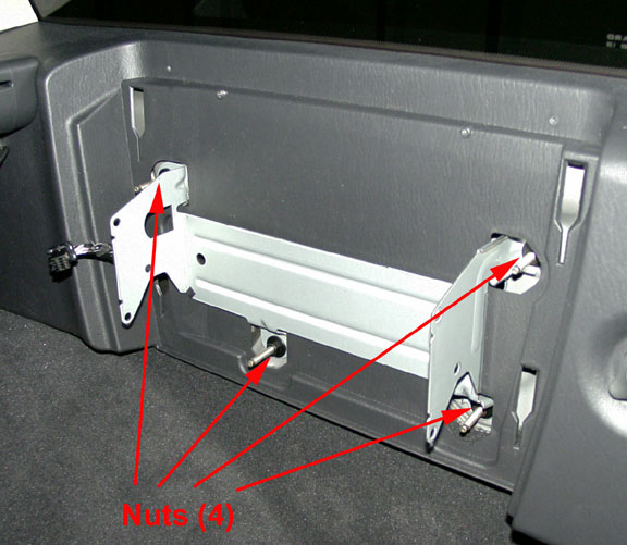
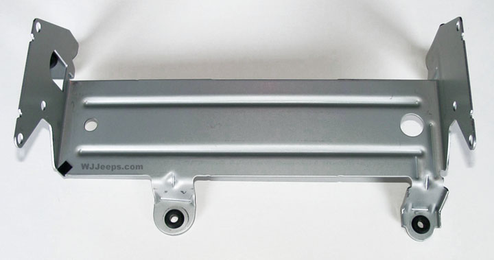
- The factory support bracket is attached with 4 nuts. A 10mm deep socket is required to remove them.
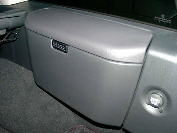
| CD Changer compartment (Passenger side cargo area) |
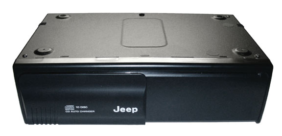
CD Changer unit. Part # P56042129AG Dimensions: 10-3/4″ W x 7″ H x 3″ D. |
CD Changer compartment cover backside view |
|---|
For WJ’s that did not come with the factory changer:
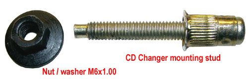
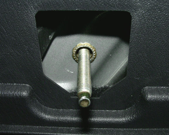
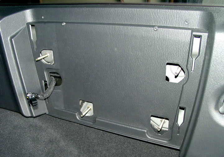
Mounting holes are pre-drilled for WJ’s that did not come from the factory with a CD changer. The mounting studs can be ordered and installed. The studs are simply pushed into the factory pre-drilled holes. When the nuts are tightened the opposite end of the bolt expands inside of the mounting hole giving them a permanent mounting.
The metal mounting bracket for some reason is not available from Mopar as a separate part, it only comes with the CD changer unit kit. Sometimes these brackets can be found on the used market. If one cannot be located, the mounting bolts can still be installed to allow the use of a custom-made bracket. It may also be possible to modify a bracket that Mopar made a few years ago for the FM modulated CD changer system. The bracket is a little narrow but redrilling mounting holes may make it fit. Mopar mounting bracket P/N 82204864
Location of factory holes for the bracket studs
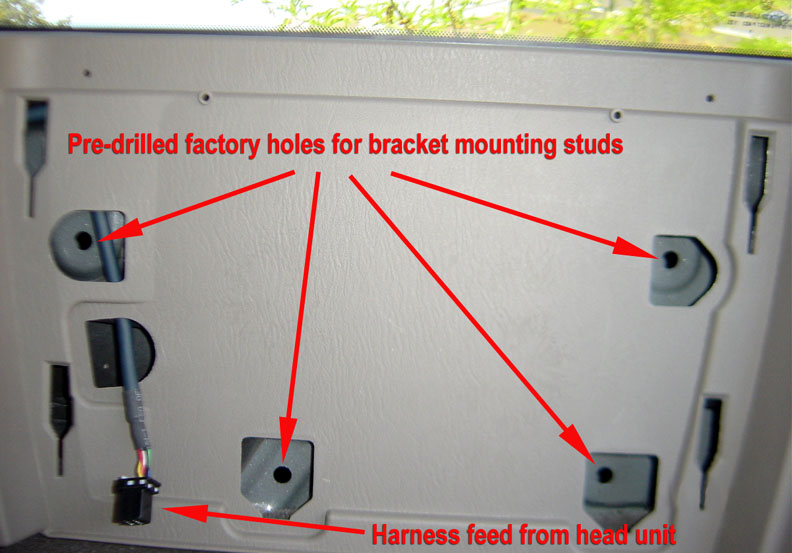
Changer bracket mounting stud and nut