Welcome to the JeepSpecs.com feature of WJ Generation Jeep Grand Cherokee 2002 JL audio system. Did we miss anything? Please get in touch with us and let us know!
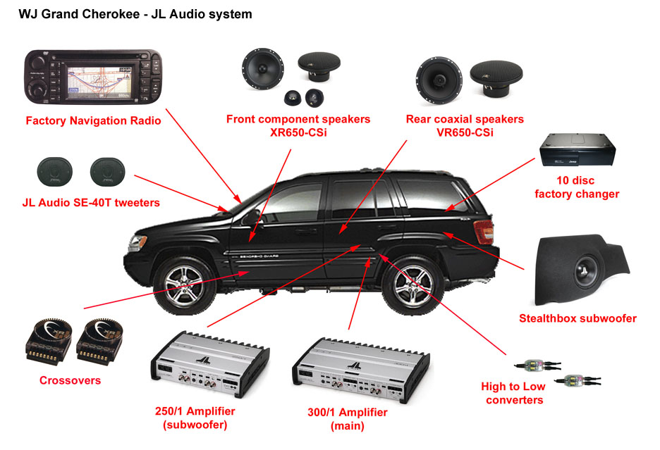
This system upgrade is patterned off of a similar installation by Jeep enthusiast and mods expert Chris Henry. As he noted in his write-up, the difference between the factory Infinity system and the JL upgrade is nothing short of amazing, and we couldn’t agree more. There are hundreds of combinations out there of different audio components that can be used in system upgrades. The JL speakers and amps have proven to work together very well, even for those wanting to keep the factory head unit. Certainly the sky is the limit if one wants to really get carried away with car audio, but the sound quality, clean installation, and other advantages of this system (or similar) should appeal to a large percentage of WJ owners out there.
After selecting the components, the next most important decision is whether to self-install or have someone else do it, professional or otherwise. The best advice is to consider this carefully. If you have the knowledge and skill you may be better off to do it yourself, saving hundreds of dollars in labor costs. More importantly, you know that the work was done exactly the way you wanted, and how it was done. If you decide to have a car stereo shop do the work, check them out thoroughly and talk to others who have had premium car audio systems installed. Inquire about the skill and experience of the installers and go over every step of the installation process. Pay at least a portion of the bill with a credit card. This can be very important for leverage should you run into any resistance in trying to get any initial problems or quirks with the equipment or installation (if any) taken care of.
Careless and sloppy installation is something you don’t want. Door and trim panel components need to be removed and replaced with care. Holes should be accurately and carefully drilled, the correct size, and only where and when necessary. It’s always recommended, of course, to keep the factory wiring intact. Any connections to these wires should be soldered and insulated whenever possible. Shrink tubing, wire ties and plastic wire loom are a necessity. Unsecured wiring and connectors may rattle, become loose, or get in the way of things like power windows
If self-installing, a Factory Service Manual can be very useful, especially when disassembling different parts of your Jeep and also for important safety precautions. Whether you are installing the system yourself or not, read the component manuals from front to back ahead of time. In some cases there are different mounting options as well as other information worth knowing about.
Every attempt has been made to insure the accuracy of the dimensions, specifications and other information contained on these pages. It is presented here for informational purposes only and the author cannot be responsible for any damages as a result of anyone using any of the techniques or procedures described herein. Proceed with caution, skill, and a little common sense and the results will more than pay off.
See also: Factory audio component removalandFactory radios and audio systems.
1. Factory AM/FM/Cassette/CD Player
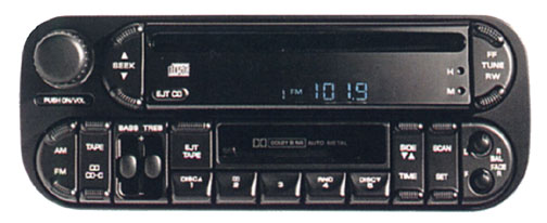
AM/FM Stereo/Cassette/CD player
Model code RBP
CD Changer Controls
Capable of Playing CDR’s
AM: Maximum Sensitivity: 12dB (uV) S/N Ratio: 50dB
FM: S/N Ratio Mono: 55dB ST: 50dB
Five Button Preset Memory w/Set Button – 10 AM and 10 FM Station Memory
FM Ignition Noise Killer
Seek and Scan Tuning
32 Watt Bridge Audio System (8W at 5% THD, 8 ohms load – 4 Amplifiers)
Electrically Controlled Tape Deck w/Fast Forward and Rewind
Auto Reverse Cassette Including Auto Load and Music Search
Automatic Metal Tape Equalization
Dolby B Noise Reduction (cassette mode)
Forward Skip, Reverse Skip to Search for the Beginning of Each Song
Random Play on CD
Part # 56038586AG
2. Factory 10-Disc CD Changer
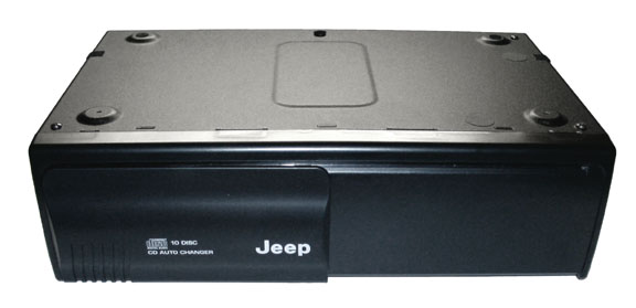
Rear cargo area mount
3-Beam laser tracking (for CD-R playback)
Anti-vibration damping
Signal-to-Noise Ratio: 95dB
Channel Separation: 80dB
Frequency Response: 5 – 20,000Hz (+/-1dB)
Total Harmonic Distortion: 0.008% (at 1kHz)
Wow & Flutter: Below Measurable Limits
Dimensions: 10-3/4″ W x 7″ H x 3″ D.
Part # 56042129AG
3. JL Audio SE-40T Tweeters
2.5+” Tweeters
Recommended Amp Power: 5 – 120 Watts
Upper-dash mounted (replacing factory Infinity tweeters)
Tweeter mounting depth: 5/8″
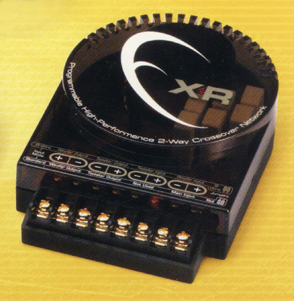
4. JL Audio XR650-CSi component speaker system (front doors)
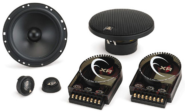
The long-throw 6.5″ component woofer features a mineral-filled, polypropylene cone body with a butyl rubber surround and a highly optimized motor system, delivering stunning mid bass impact and midrange quality. The tweeter is a neodymium magnet, ferrofluid-cooled, 1-inch (25mm) aluminum dome with a synthetic rubber surround that damps unwanted ringing for smooth, non-fatiguing output.
The component tweeter features JL AUDIO’s exclusive RSR mounting system, permitting precise alignment after installation for optimum performance. Competition-ready, high-end crossover networks with super-premium polypropylene capacitors, super-premium inductors, adjustable tweeter level and solid-state tweeter protection round out the package.
2-way System:
6.5-inch (160 mm) Woofer
1-inch (25 mm) Aluminum Dome Tweeter
70W Continuous Power Handling
Recommended Amp Power: 25 – 150 Watts
89.5 dB Efficiency @ 1W/1m
Woofer mounting depth: 2.81″ (approx. 2-13/16″)
Tweeter mounting depth: 0.625″ (5/8″)
Frequency Response: 48 Hz – 25 KHz ą 3 dB
Nominal Impedance (tweeter): 8 ohms
Nominal Impedance (woofer): 4 ohms
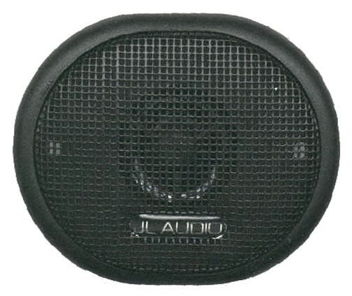
5. JL Audio XR650-CX 6.5″ Coaxial speakers (rear doors)
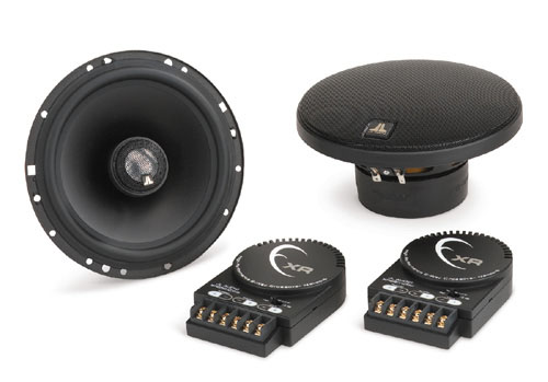
The long-throw woofer element features a mineral-filled, polypropylene cone body with a butyl rubber surround and a highly optimized motor system. The tweeter is a neodymium magnet, ferrofluid-cooled 1-inch (25mm) aluminum dome with a synthetic rubber surround that damps unwanted ringing for smooth, non-fatiguing output.
The tweeter is mounted at a fixed 15 degree angle with a swivel feature that allows it to be aimed for optimum sound quality in the vehicle. Outboard crossover networks with polypropylene capacitors and premium inductors feature adjustable tweeter output level and solid-state tweeter protection.
6.5-inch (160 mm) Coaxial speaker
1-inch (25 mm) Aluminum Dome Tweeter
70W Continuous Power Handling
Rec. Amp Power: 25 – 150 Watts
89.5 dB Efficiency @ 1W/1m
Mounting Depth: 2-13/16″
Installation diameter: 5-1/2″
Frequency Response: 48 Hz – 25 KHz ą 3 dB
Nominal Impedance: 4 ohms
6. JL Audio Stealthbox subwoofer (rear cargo area)
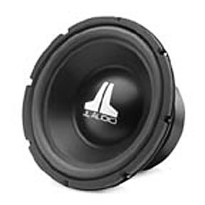
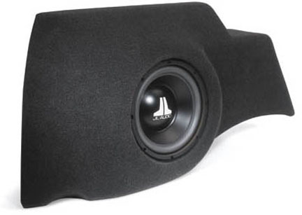
Consists of one model 10W3-D2 10″ woofer in a sealed enclosure. Exceptional excursion capability and highly linear motor and suspension designs combine to deliver maximum performance from higher power levels. Wired for 4 ohm mono. Installs in the driver side rear corner of the cargo area, sacrificing little useful cargo space. The subwoofer is protected and concealed by a color-matched, carpeted steel grille.
Diameter: 10 inches (250 mm)
85.3 dB Efficiency @ 1W/1m
Continuous Power Handling: 250 Watts
Magnet Diameter: 5.9375″
Voice Coil: 2.25″ diameter, 4-layer, Kapton former
Stealthbox air volume: .6 Cubic feet
Nominal Impedance: Dual 2 Ohm
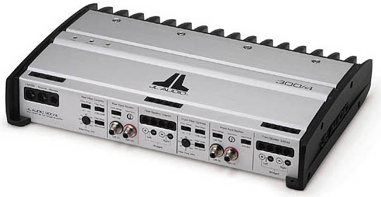
7. JL Audio 300/4 main amplifier
Features a cast-aluminum heat sink with vertically-oriented fins that are highly effective at dissipating heat from the amplifier via convection and radiation. The amplifier Performance chart shown above was made by by CarSound.com.
Rated Power (stereo): 75 W RMS x 4 @ 1.5 ohm-4 ohm (11V-14.5V)
Output Power (resistive) min. output 20 Hz – 20 kHz @ 1%THD+N, all Channels driven into 4 ohms: 97 watts x4 @ 14v, 90 watts x 4 @ 12.8v
Idle Current Draw: 1.6 amps
Current Draw @ 1/3 max power: 28.8 amps @ 62.3 watts x 2
THD at Rated Power: <0.03% @ 4 ohm
S/N Ratio: >108.5 dB below rated power (measured at -121.5)
Frequency Response: 5 Hz-30 KHz (+0, -1dB)
Voltage for Rated Output: 128mV to 8.3 volts
Distortion at Rated Output @ 1 kHz: 0.007% @ 150 watts x 2
Power-Up Noise: 0.5 dB SPL
Power-Down Noise: 0.3 dB SPL
Damping Factor: >200 @ 4 ohm per ch./50 Hz
Input Range: switchable from 200mV-2V RMS to 800mV-8V RMS
Dimensions: 13.4″L x 9.25″W x 2.36″H
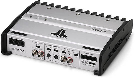
8. JL Audio 250/1 subwoofer amplifier
Utilizes a new Class D circuit which represents a significant advance in subwoofer amp design. While Class D amplifiers are well known for outstanding efficiency, they have also been known for less than spectacular sound quality due to weak damping of the driven load. Damping factor is critical to subwoofer amplifier performance as it provides the necessary force to control the high moving mass of subwoofers. Poor damping results in degraded transient response (sloppy sounding bass) and irregular frequency response. JL Audio’s Patent-Pending Class D output circuit utilizes a discrete control section and a unique feedback loop design that results in a damping factor greater than 500 at 4 ohms (>250 at 2 ohms). This is vastly higher than other Class D designs and also higher than most Class AB amplifiers. The benefit of this exclusive JL Audio technology is tight, clean bass reproduction with all the efficiency of Class D.
Rated Power (mono):
250 W RMS @ 1.5 ohm-4 ohm (11V-14.5V)
THD at Rated Power: <0.05% @ 4 ohm
S/N Ratio: >95dB below rated power
Frequency Response: 5 Hz – 500 Hz (+0, -1dB)
Damping Factor: >500 @ 4 ohm/50 Hz
Input Range: switchable from 200mV-2V RMS to 800mV-8V RMS
Dimensions: 10.25″L x 9.25″W x 2.36″H
9. DEI High-to-low converters (adjustable)
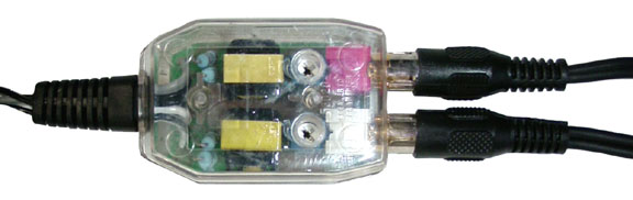
Manufactured by “DEI” (Directed Electronics, Inc.). Used for converting factory head unit high level inputs to low level amplifier inputs. Part # 55020. See also Audio Upgrade.

| Dash tweeters | Front doors | Crossovers | Rear doors |
| Amplifiers | Subwoofer | Wiring |
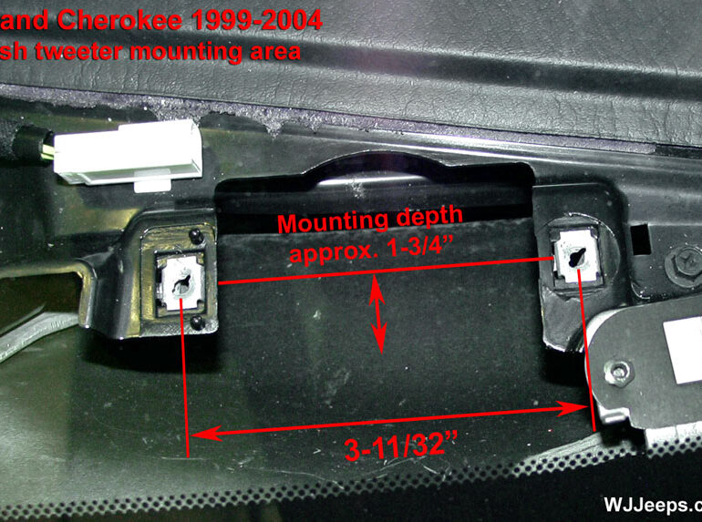
Front dash tweeters (2.5″)

JL Audio tweeters
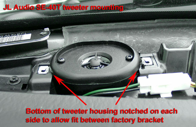
The 2.5″ front dash Infinity dash tweeters were replaced with the JL Audio SE-40T tweeters, which fit perfectly into the opening. The SE-40T tweeters originally came out in 1992 and are now considered a “budget” speaker. They can usually be found on Ebay for under $40.00/pair. There are much better tweeters on the market, but the SE-40T’s are decent for the price.
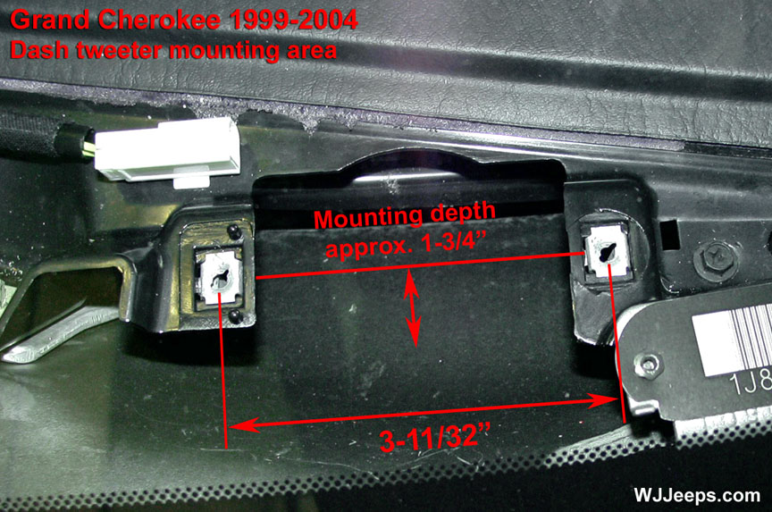
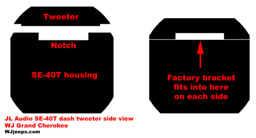
The SE-40T speakers come with a plastic housing (for surface mounting), and for this project they were installed with their housing into the dash. A small slot was cut out on the top of each end of the housing, allowing the speakers to slide perfectly and tightly between the metal factory brackets, no screws needed. There is plenty of room underneath and to the side of the installed tweeter for the wiring, and for the small capacitor and resistor (bass/power blocking) that is required when the Infinity amp is upgraded. The distance between the factory mounting holes is 3-11/32″ and the mounting depth is approximately 1-3/4″.
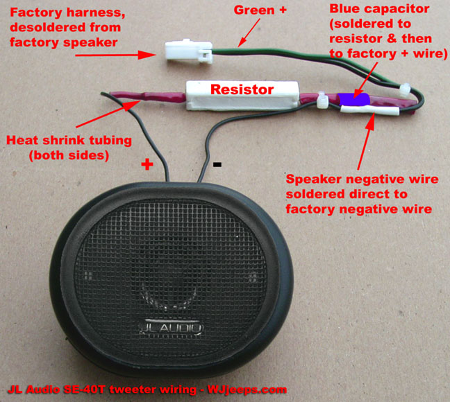
If you are installing the SE-40T tweeters in a system utilizing the factory Infinity amp, you do not need to install the capacitor or resistor shown in the above left photo. If the tweeters are too “bright” however, you can install the white resistor to bring them down a bit.
MB Quart tweeters
 OLYMPUS DIGITAL CAMERA
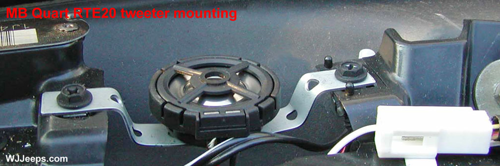
Other brands of tweeters, up to 3-inch size or so, can also be installed into the upper dash. MB Quart makes an excellent line of 3/4″ and 1″ premium “Reference series” tweeters that are of outstanding quality and are very easy to mount.
The MB Quart tweeters feature a threaded hole on the bottom which makes mounting very easy, as shown in the photo above. A head unit mounting strap was used in this installation by Jeeps Unlimited member Mike the Apeman. The MB Quart tweeters are among the best on the market. For mounting tweeters without a threaded hole on the bottom, a mounting plate can be easily made out of 1/8″ fiberboard. A hole saw bit works best to drill out the hole for the tweeter.
TIP – TWEETER MOUNTING DEPTH:
Some owners have been able to slightly increase the 1-3/4″ mounting depth by using a heat gun to soften the air duct which is just below the tweeter. For obvious reasons, great care must be taken when doing this so as to not damage the duct.
Front door speakers (6.5″ & 1″)
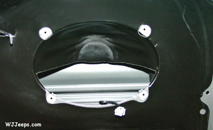
| Passenger side door | Driver side doorTemplate dimensions | Template mounting holes | Front speaker opening |
|---|
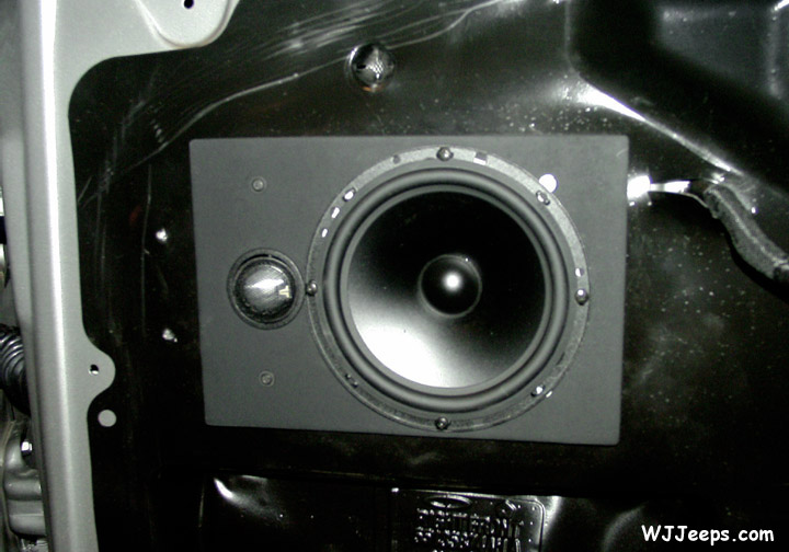
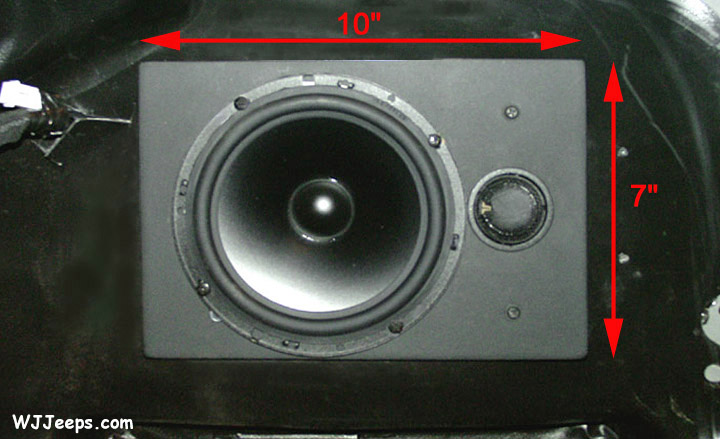
The factory Infinity 6×9 speaker was removed and a custom backing template was made to install both the 6.5″ and 1″ tweeter into the same opening. Both speakers fit side-by-side very nicely, although with very little room to spare. The new 1/4″ fiberboard speaker template was cut to a size of 10″ x 7″. All four factory holes were used to attach the plate to the door. To mark the screw locations, I simply took the factory Infinity speaker and turned it upside down onto the template, centered it exactly and then used a pencil to mark the holes for drilling. I then temporarily installed the wood plate onto the door to verify alignment and fit. While it was attached, I reached up inside the door and scribed a pencil line around the factory 6×9 opening onto the back of the wood plate. This defined the area that I had to work with to fit both of the speakers into. This step is not necessary if the templates below are used.
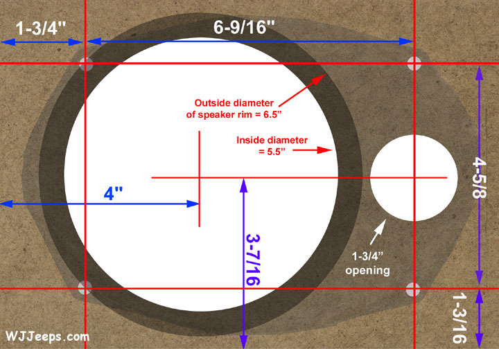


| Speaker hole dimensions | Mounting hole dimensions | 6×9 superimposed on board |
|---|
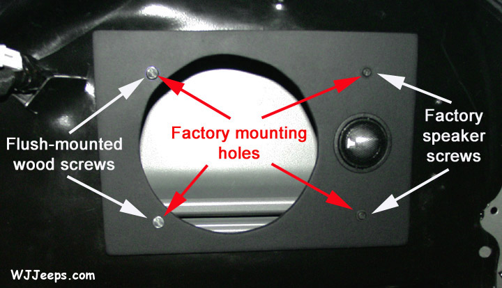
The three photos above show the dimensions for the mounting holes and the woofer and tweeter placement in the factory opening. The 6×9 image is superimposed onto the fiberboard to show the working area available for the new speakers. Click on any of the above pictures for an exact-size enlargement which can then be printed and used for a template for cutting your board. You can even cut-out the speaker holes in the printed picture and overlay it onto your door to verify exact fit before you start cutting the actual board, which I would definitely recommend. Printing the template onto thicker card stock paper will give you a more rigid example to work with.
Since there’s not a lot of room to work with, the speakers have to be mounted fairly close together. Because of this, the rim of the 6.5″ woofer slightly overlaps two of the factory mounting holes. For these two holes, I used two wood screws which I countersunk so that they would be flush on the template, allowing the speaker to sit flush over them. I drilled the 4 plate mounting holes using a 3/16″ bit.
With a compass, circular cut-out marks for the woofer and the the tweeter were drawn, spacing them as even as possible into the allowable opening area. A 1-3/4″ holesaw blade was used to cut the tweeter opening, and a jigsaw used to cut the 5-1/2″ hole required for the woofer. Both boards were lightly sanded, including the edges and around the speaker mount holes, and then cleaned with a damp rag. Lastly, a couple coats of black spray paint was applied so they would blend nicely into the doors and also to prevent fiber dust from coming off them. The finished boards were then attached to each door with the tweeters pre-installed, and then a thin band of rope caulk was added around the inside perimeter of the woofer housings before they went into the template. Four 1/8″ holes were drilled to mount the woofers. Both the supplied screws and spring-clip nuts were used, allowing the speakers to be securely fastened.
Pre-made plastic speaker templates are available from companies like Scosche. See Speaker templates in the Audio accessories section for more information.
Front crossovers
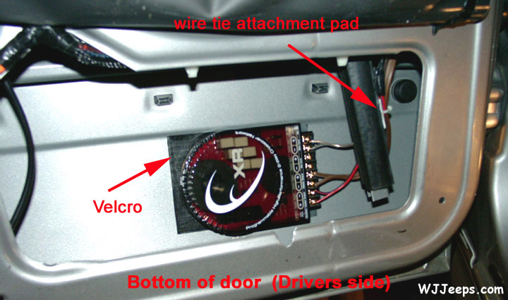
Note: JL Audio recommends that their crossovers NOT be mounted inside of the vehicle doors. Doors often get wet on the inside, which can damage your crossover networks and could potentially damage your entire sound system.
I decided I would take a chance, being that the WJ is garaged and the doors are a very convenient place to mount them. On the door ledge above the crossovers I duct taped a small 8″ wide sheet of clear plastic that hung over them, keeping them protected from any direct moisture. If you decide to install your crossovers in the doors, proceed at your own risk!
The component system crossovers were mounted inside the bottom of each door and attached with industrial strength Velcro. The entire backs of the crossover housings were covered with Velcro, using two strips each a couple inches wide. I cleaned the area of the door where they were to be mounted with rubbing alcohol and then very lightly sanded the same area so that theVelcro backing would stick firmly. Wiring was secured to the back of the window guide to keep it out of the path of the window. All other speaker wiring was attached where necessary to keep it out of the path of the windows and to prevent any rattling.
Rear door speakers (6.5″)
WJ Speaker cut-out opening: 5-3/4″ diameter WJ Speaker opening depth (to glass): 2-7/8″
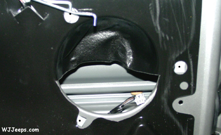
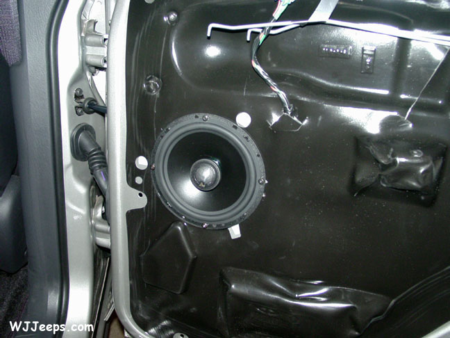
The new rear door speakers fit nicely into the 5-3/4″ diameter factory openings, with about 1/8″ of play all around. The mounting depth of the speaker was such that the back of the speaker came very close to the window glass. A 1/8″ fiber board spacer ring was cut and installed around the speaker opening to bring it out another 1/8″. The spacer was affixed directly to the door metal with a bead of rope caulk around it for cushioning. The waterdam cover was placed over the spacer and then the speaker was placed in the opening and centered. Centering is important as there is not a lot of extra room at the edges to reach the door metal. The waterdam material had to be cut a little to allow the thicker speaker to fit properly. Four 1/8″ holes were drilled to mount the speakers. Both the supplied screws and spring-clip nuts were used, allowing the speakers to be securely fastened.
Pre-made plastic speaker templates are available from companies like Scosche. See Speaker templates in the Audio accessories section for more information.
Rear crossovers

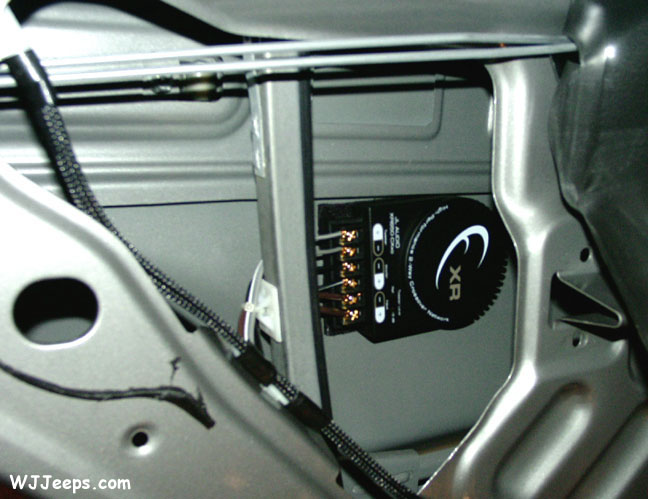
As in the front, the crossovers were mounted inside each door and attached with industrial strength Velcro. See note above under Front Crossovers per the warning about installing crossovers in doors.
Amplifiers
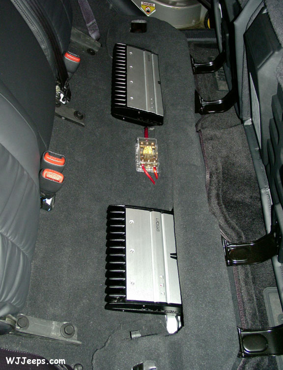
The Infinity amp and bracket assembly were removed, as well as the jack tools located under the rear passenger seat. The two JL amps were then mounted underneath the rear seats. The 250/1 subwoofer amp was installed on the passenger side, and the 300/4 amp on the drivers side. In order to fit the amps in this location, the metal rear crossmember had to be notched out on each side. This allowed the amps to be recessed about 2-1/2″ into the beam. The factory carpet neatly fit into and around the new opening. Each amp was attached to the thick carpet with just two short screws, one in each upper corner (they will actually stay nicely in place without any screws).
All of the wiring to and between the amps was run through the crossbeam. The fused 4 gauge wire feed from the battery was run to a fused junction block located between the amps. The block then fed a power line to both amplifiers. There is room for the amps to “breath” by way of the gap between the bottom of the seats and the top of the crossmember. There are also other openings around the seats where hot air can escape.
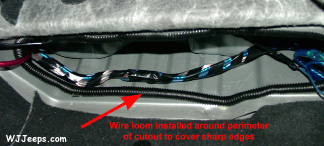
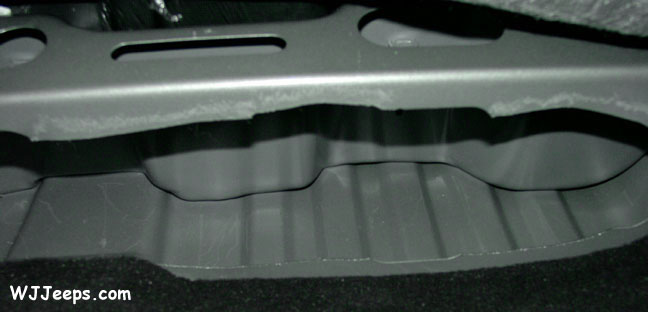
Shown here are views of the crossbeam opening cutouts. The top photo shows the drivers side (looking forward) where the 300/4 was installed. The installers implied that this was going to be cut cleanly, but as you can see they cut the top pretty crooked. If I had known this I would have done it myself. I added wireloom around the openings of the cutout area and secured it every 6 inches or so with hot glue, as seen in the second photo (passenger side, looking forward). This worked nicely to cover the rough edges of the opening and also allowed the bottom of the amps a smoother area to “rest” on than bare metal. In order to retain the original strength of the crossbeam, I plan on adding a piece of 1/4″ sheet metal on each side, custom cut to fit in front of the entire opening, with a rectangular area cut out for the amps to slide into. They will then be bolted to the crossmember
Stealthbox subwoofer
| Cargo net removal | Mounting bolt | 99-’01 Stealthbox | ’02 Stealthbox |
|---|
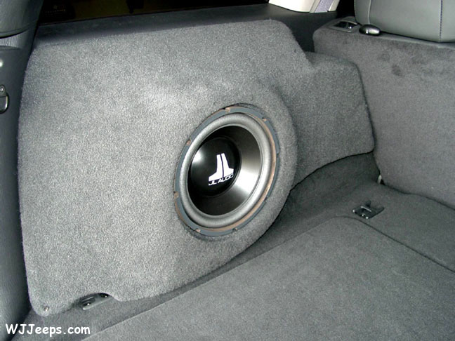
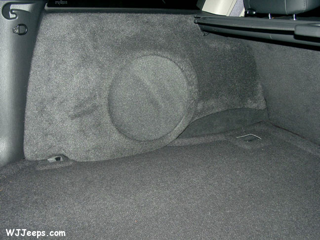
The Stealthbox 10″ subwoofer fits nicely and takes up very little cargo room. It is installed with with just one bolt, drilled into the wheel well. This is a very important and worthwhile addition to the sound system. Chris Henry was right when he said “…the sealed enclosure holding the 10W3 pounded out bass notes with tightness and authority…and can handle anything you throw at it.” It will indeed vibrate the entire vehicle if so desired (and the people inside), but even at reasonable listening levels the impact and clarity is stunning.
The Stealthbox has recently undergone a slight modification in order for it to fit properly in 2002 models. For some unknown reason, Jeep moved the recess mounting slot for the cargo shade 1-1/4″ further towards the rear. The previous model Stealthboxes covered over this area on the 2002 WJ’s preventing the mounting of the cargo shade. All Stealthboxes manufactured after June 1, 2002 are now recessed back further along the top right side to allow room for the cargo shade. The part number remains the same (even though I suggested otherwise to avoid confusion) and the new model will now fit all WJ’s from 1999-2002. If you have a 2002 or later WJ, make sure that the dealer is ordering factory direct rather than from some distributor who may still have the earlier versions in stock, and that your model year is specified on the order form.
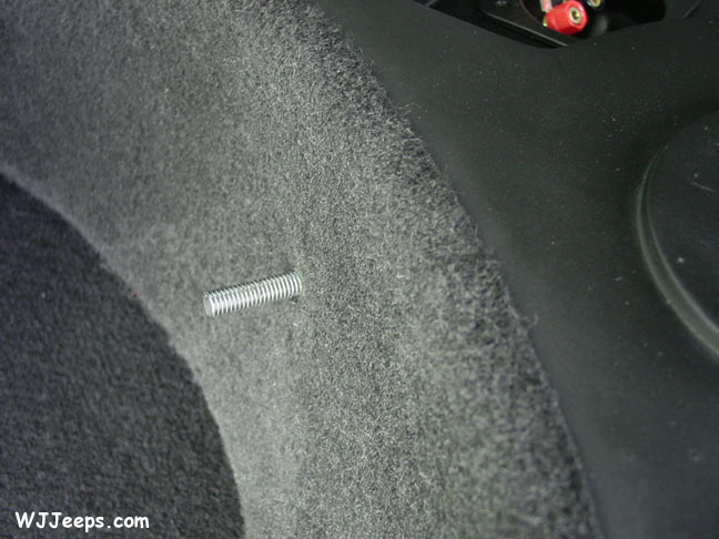
I found the supplied 3/8″ x 1-1/2″ bolt much too short to mount the subwoofer to the wheelwell (this has now been addressed with a new bolt design). The directions tell you to drill the hole in the wheelwell, place the subwoofer into position, and then feed the bolt up through the fender. After a failed effort of trying to line up the bolt to the subwoofer, I gave up and went to the hardware store and bought a longer 2-1/2″ bolt. I also picked up a rubber 3/8″ grommet to place in the new fenderwell hole. The longer bolt was still a little difficult to line up, as just being off slightly allowed the bolt to easily crossthread. I finally ended up cutting off the head of the bolt. I threaded it a few turns into the subwoofer enclosure, and then placed the subwoofer on the fenderwell to align the bolt through the grommet and hole. Once in place, from underneath I put two nuts at the end of the bolt so that I could thread it deeper into the subwoofer. Once that was done, I removed the two nuts, added some sealant around the hole, added the washer, and bolted one nut and lockwasher back on to tighten it up.
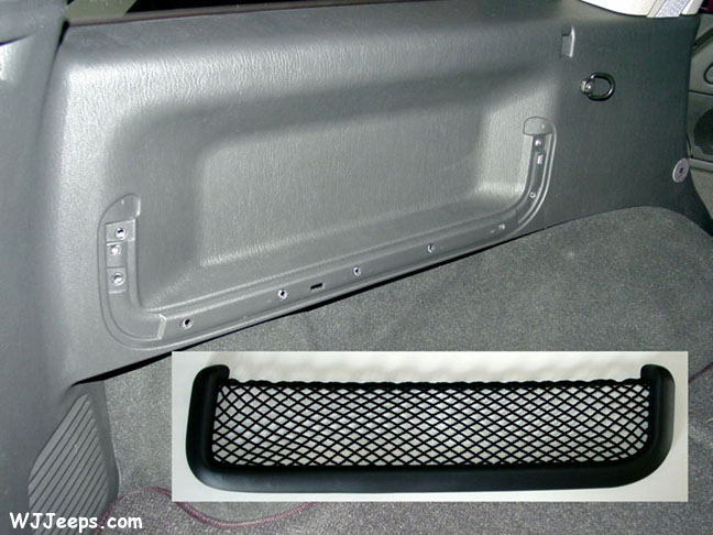
NOTE: 2001 and later model WJ’s have a net attached to the side pocket storage recess, right where the subwoofer mounts. The net assembly has a plastic oval frame molding that when in place protrudes out from the side trim piece. For a better subwoofer fit, this storage net can be removed, but you must remove the entire side trim piece to get to the back to remove it. That involves removing the rear headliner trim cover, one screw in the left rearward cargo floor molding, the rear upper left corner trim piece, and the main left side rear trim piece. In order to remove the main trim piece, you must first remove the two black metal cargo hooks. The cargo net is installed with plastic rivets which must be drilled out in order to free the net frame. I used a 3/8″ drill bit and drilled just slightly deep enough to free the rivets and remove the frame assembly.
For directions on removing the rear trim, see Cargo area left trim piece removal
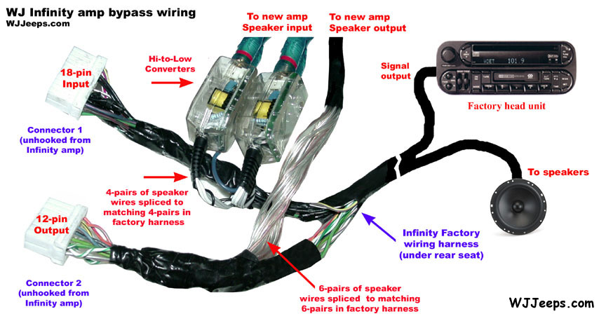
Wiring
| Power wiring to battery | JL system wiring |
|---|
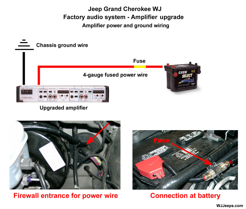
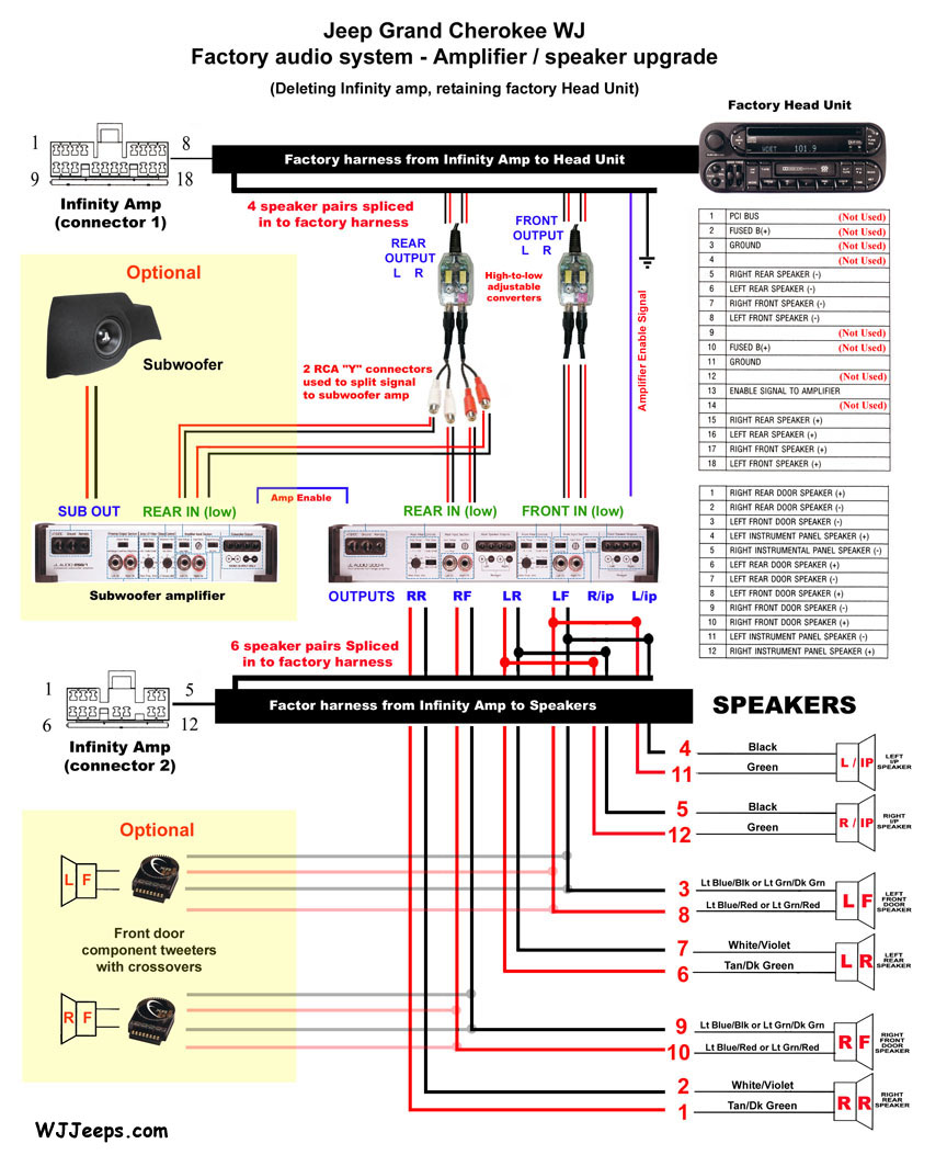
Click Here for a printer friendly version of the main diagram shown above left.
The installation of this system was simplified by using the original factory speaker wiring. It was was easy although somewhat time-consuming to splice the 22 needed wires into the two factory Infinity amp harnesses. The harnesses were in a perfect location since the new amps were going into the same area under the seats. The wires can be spliced just a few inches back fro m each of the connectors that were unhooked from the Infinity amp. The top photo at left shows a detailed diagram for the speaker and amplifier wiring.
The upper right photo shows the power, ground and amplifier control wires. The two main power wires from the amps are connected to a fused breakout box between the amplifiers, and from there a 4-gauge power line was run along the left baseboard, through the upper firewall via the existing grommet, and to the battery. The power line was fused again at the battery for added protection.