
Welcome to the JeepSpecs.com in-depth page on WJ Generation Jeep Grand Cherokee lamp bulb removal. We have organized as much information as we could find into a helpful article below. Is something incorrect or missing? Please get in touch with us and we’ll fix it!
Interior bulb removal
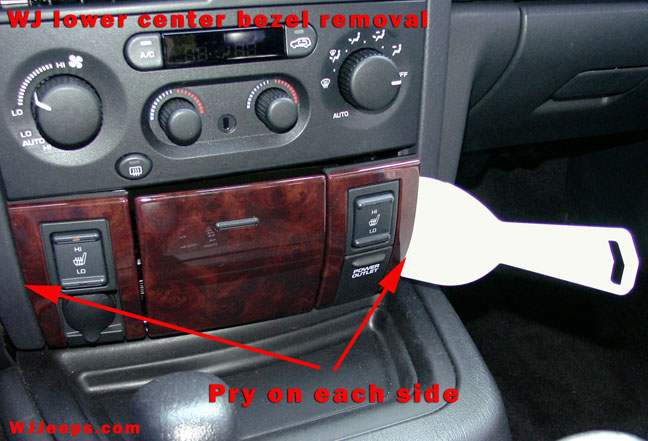
Ashtray (# 161) / Lower center beze
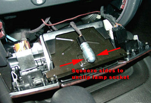
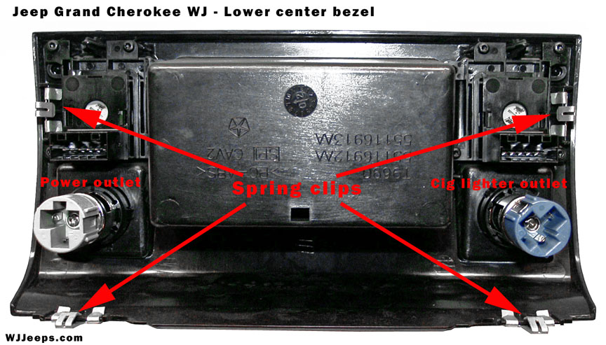
The center bezel assembly is held in place by strong snap clips near each corner which can be gently pried out with a hard plastic putty knife. Once loose the assembly will slide straight out. The ash tray light socket is attached to the top of the tray with a spring clip which is unhooked by squeezing and tilting it out at the base.
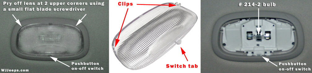
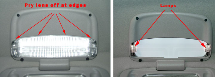
Cargo area (# 214-2)
Using a very small flat blade screwdriver, pry the lens away from the corners as shown in the left photo. When replacing the lens cover, align the push-button switch tab into its slot first and then snap into place the two lock clips.
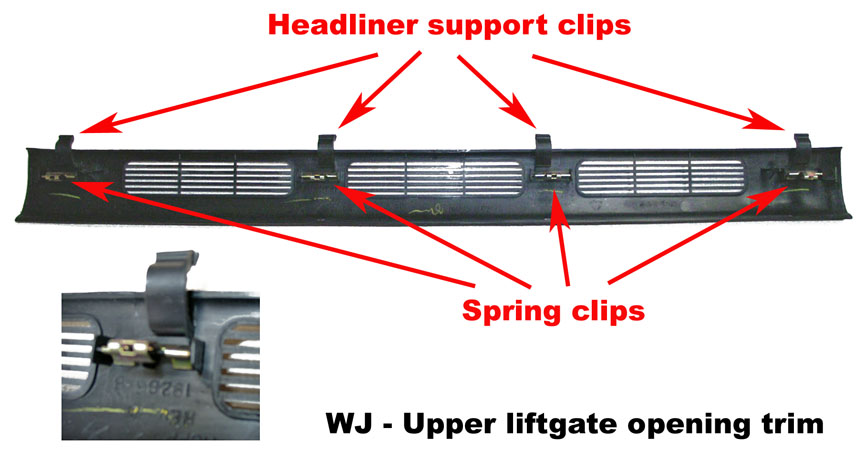
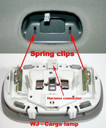
If you need to remove the cargo lamp housing, remove the liftgate upper trim piece to gain access to the lamp housing. The trim piece is held in place with four spring clips. Pull down to release the clips, and then pull straight back to disengage from the headliner. The lamp housing is attached with two spring clips..
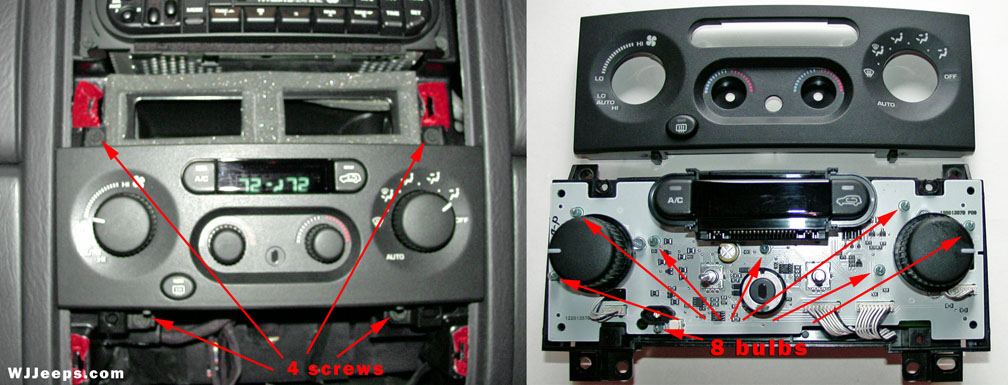
Climate control, Automatic (P/N 5013123AA graphics, P/N 5013124AA knobs)
Eight climate control lamps are soldered onto the internal circuit board of the Automatic Zone Control assembly. These are unlikely to burn out for many years, but some owners have wanted to color the bulbs. To remove the AZC unit, the radio bezel and the lower bezel assembly must be removed. Both bezels are pried out using a flat hard plastic blade tool (see ashtray lamp section above). The AZC unit is held in place by 4 Phillips screws. After removing the screws slide the unit out and unplug the two wiring harnesses in the rear. To open the unit, remove the two smaller knobs in front by pulling them straight out. Then remove the 4 rear screws with a Torx T-20 screwdriver to separate the front plate.
Note: The AZC controllers for model years 2003-04 were reprogrammed. The factory suggests that these not be installed in 1999-2002 vehicles. Also, the AZC controllers can not be installed into models with manual controls.
Cluster illumination (#103 Jeep P/N L00PC121 for backlighting and # PC74, Jeep P/N L000PC74 for warning/status lights)
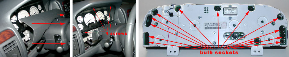
The gauge cluster is surprisingly easy to removed. First, remove the cluster bezel trim piece that is above the steering wheel. It is held in place by 4 spring clips, one at each corner, and pulls straight out. On the left side, you can reach your thumb behind the bezel rubber at the tilt wheel lever cut-out and pull forward. 2003-2004 models do not have the rubber piece but you can still reach behind the bezel in the same although there is less room for your fingers. If so equipped, you’ll need to unhook the power pedal harness on the back of the switch.
Next, remove the 4 phillips screws on the cluster assembly, two along the top and two on the bottom. At the two upper screw holes there are tabs that must be slightly pried down to release the cluster, which you can then pull outward and away. There is plenty of slack allowed to conveniently unhook the single 9-wire/12-slot harness.
Note: The amount of replaceable bulbs and their locations may vary somewhat by year, model and options. Typically, there are five #103 bulbs used for backlighting the cluster (except lectroluminescent clusters) and anywhere from 12-20 PC74’s used for the different status and warning lights. To remove the sockets, twist one-quarter turn. The bulbs can then be wiggled out from the sockets.
WARNING: On vehicles equipped with the premium instrument cluster, the cluster circuitry provides an alternating current to supply power to the electroluminescent illumination lamp through a pigtail wire and connector that is accessible at the back of the cluster housing. Use proper precautions when handling this unit during diagnosis or service to avoid electrical shock and possible personal injury.
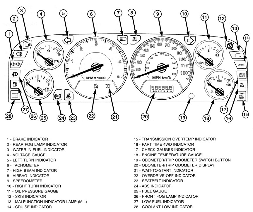
Cluster layout and descriptions, example shown is from 2002.
Courtesy light, front doors (# 192)
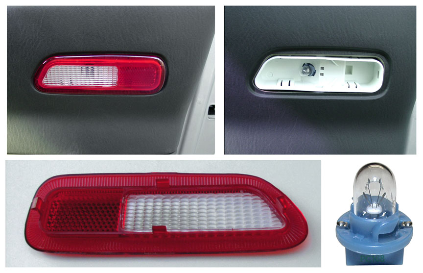
Note: Lens cover = p/n 56005077 (left) and p/n 56005076 (right)
The lens cover can be pryed off from the front with a small flat-blade screwdriver. However, at least for model years 2002-2003, the bulbs are part of the socket and must be removed from the back, inside the door panel. The door courtesy lights were eliminated starting with the 2004 model year.
Removing the bulb is actually quite easy to do without having to remove the entire panel.
1. Remove one screw, the phillips screw located inside the door pull.
2. With a flat blade tool (like a hard plastic putty knife), pry the lower outside edge of the door panel up enough to unfasten the side trim clips, and perhaps one more in the bottom area.
3. Reach inside the door panel edge and remove the bulb/socket from the back of the housing (turn socket 1/4 turn counter-clockwise).
Note: When pushing the side of the door panel back on make sure the clips are aligned with their holes.
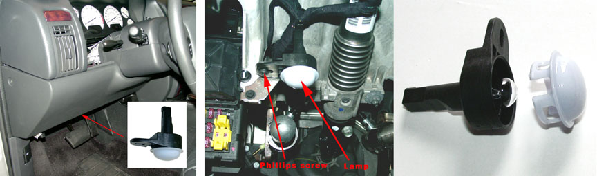
Courtesy, under dash (# 906)
The bulbs for the two under dash courtesy lights can be changed by simply prying off the white dome covers which are held in place with plastic tabs. Both sockets can be accessed without removing any trim pieces or other parts.
Dome / Reading (# 192)
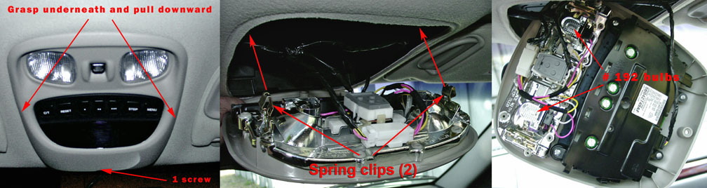
Two dome / reading lights are located in the overhead console. To remove the console, remove the single phillips screw located near the windshield side. The screw should be removed with a non-magnetic screwdriver as to avoid interference with the compass. The console is also held in place by two spring clips. Grab the console from the sides, wedging your fingers underneath it, and carefully and firmly pull it straight down.
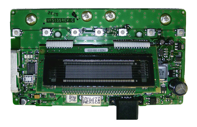
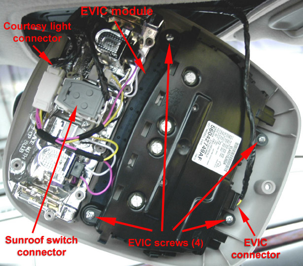
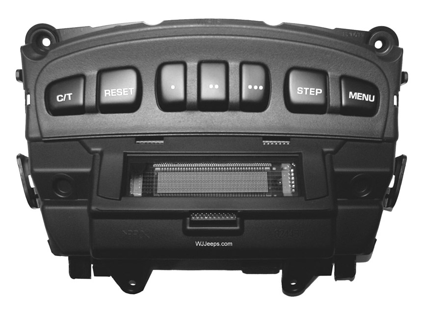
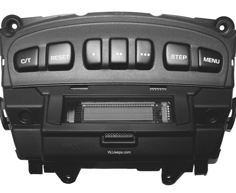
EVIC (Electronic Vehicle Information Center) (Mopar # 04437661)
Four bulbs are used for backlighting the C/T, Reset, Step, and Menu buttons on the EVIC. The four bulbs can be seen along the top of the circuit board, shown in the photo above right. To access the bulbs, the overhead console must first be removed (see directions above under “Dome / Reading”). Remove the four phillips screws that attach the EVIC module to the overhead console housing (shown in center photo above). The EVIC module can be opened by prying the tabs on the side. The circuit board will then lift right out and the bulbs can be replaced.
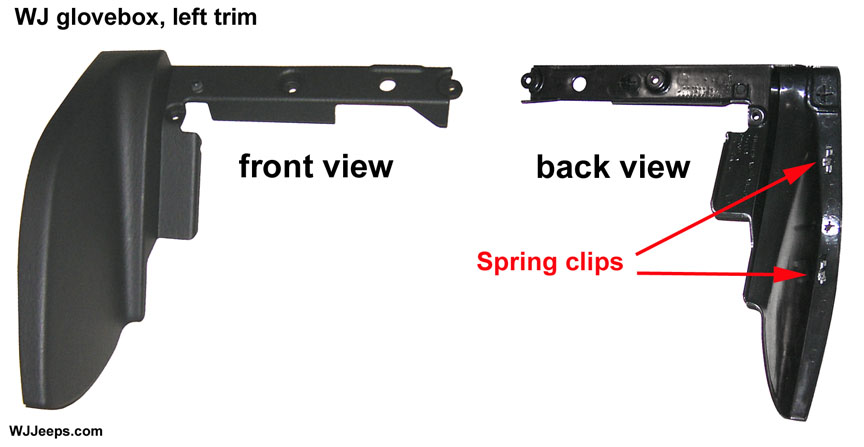
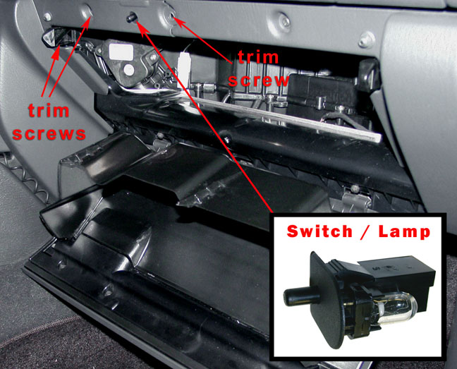
Glove box (# 194)
1. Empty contents of glove box.
2. Loosen or remove bezel trim piece – The bulb socket can be accessed by removing just two of the three bezel cover screws, which will allow the top right of the bezel piece to be pulled out far enough to pull the socket through. However, to make things a little easier it is not too difficult to remove all three screws and the trim bezel entirely. It is held in place by two strong spring clips. Grasp the bezel at the bottom, around the back edge, and firmly pull or jerk it forward and away.
3. Roll the glovebox down. This is done by reaching in to the top inside of the glove box with both hands, in front of the sharp plastic guide pins, and with your middle fingers pushing each rubber stopper up and out of the way to let the pins pass by and the glovebox drop down. Note: Some models may feature a pneumatic glove box damper on the right side of the glove box. The arm of the damper must be lifted upwards to remove it from its keyed slot.
3. The socket is held in place with two plastic retaining tabs, one at the top and one at the bottom of the switch. It’s a tight fit to get your finger over the top clip to try and release it, but that is not really necessary, the socket can be removed by just depressing the bottom tab. To do this, use your right hand middle finger to press up on the bottom of the lower retaining tab, while at the same time reaching in and under the socket with your left forefinger and thumb to wiggle and push the socket forward. This will release the socket from the bottom at an angle, enough so that you can now grab it from the front lip cover while still pushing it from the back to wiggle it free from its mounting hole.

Pull handles (# 214-2)
Using a very small flat blade screwdriver, pry the lens away from the housing on the left side as shown in the photo. When replacing the lens cover, align the push-button switch tab on the right side into its slot first, and then snap the two lock clips on the left side into place.
Sunvisor vanity (# 6501966)
The lens for the vanity lights can be pried off with a small flat screwdriver, starting in either of the top corners. There are two “fuse” style bulbs in each housing. The bulbs are available from your Jeep dealer.
Exterior bulb removal
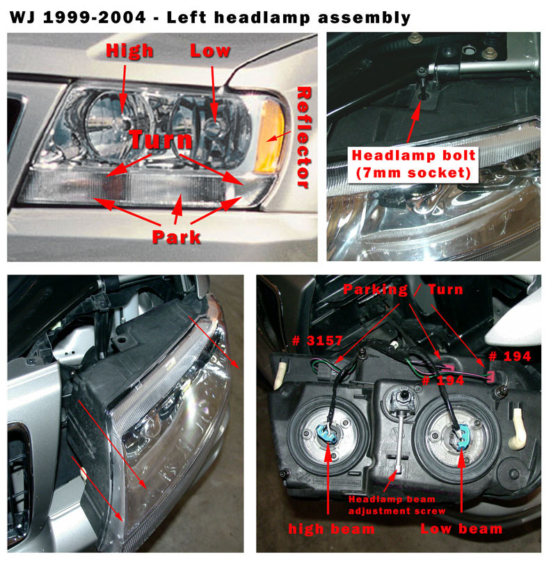
Front: Headlamps, Parking, Side marker, Turn signal (5 bulbs)
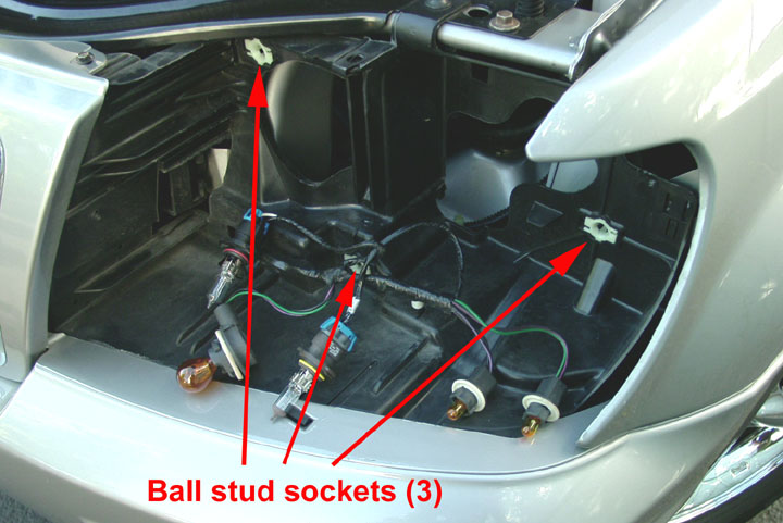
Open the hood, and using a 7mm socket remove the long headlamp jackscrew, located as shown in the photo above, 2nd from left. Grasp the headlight assembly on the upper inboard and lower outboard corners and wiggle and pull very firmly outward to disengage the 3 ball stud alignment posts from their sockets (be cautious of the sharp edges of the grille and fender areas surrounding the headlamp). The location of the 3 mounting sockets and ball studs is shown in the photos below.
Note: Use caution when removing and handling the headlamp assembly. The headlamp beam adjustment shaft on the rear center of the housing is very brittle and can easily be broken.
Tip: Apply a small amount of grease to the 3 alignment posts when reinstalling the headlamp housing, this will make it easier to remove in the future.
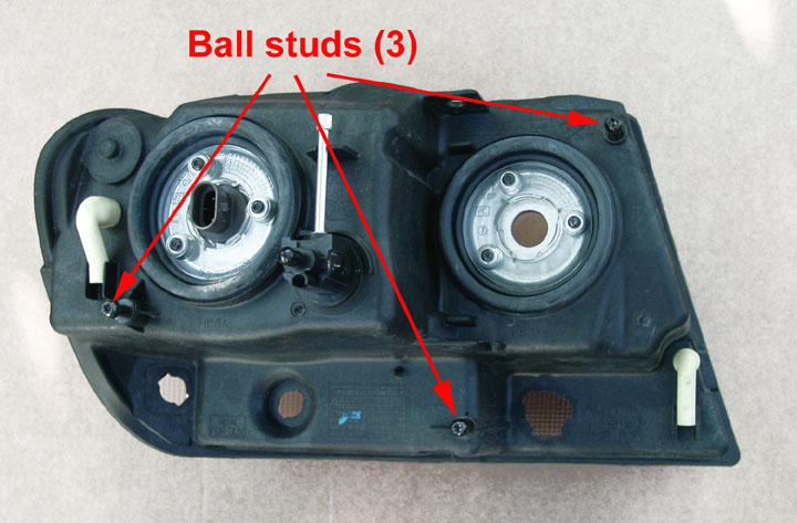
Headlamp mounting area and rear of housing, showing ball stud fasteners.
Front: Foglamp (1999-2003) (# 9055)
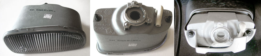
The foglamp bulbs can be accessed and removed from underneath the bumper without tools, although it is a tight fit. Turn the lamp socket 1/4 turn counter-clockwise to remove from the rear of the housing. Note that the screw in the front of the foglamps is for alignment only and does not remove the outer lens. The fog lamp housing is attached to the fascia with two nuts which can be removed with a 10mm socket.
Fog lamps can be added to most Laredo model WJ’s that came from the factory without them. Mopar kits are available that include two fog lights, wiring harness, and steering column switch. Click Here for part numbers and other information on these kits.
Front: Foglamp (2004) (# 9145)
The foglamps were changed to a round style for the 2004 model year.
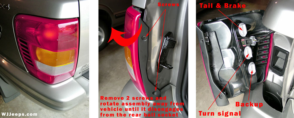
Rear: Brake, Back-up, Tail, Turn signal (3 bulbs, all # 3157)
To access the rear bulbs, open the liftgate and remove the two phillips head screws from the side of the housing as shown in the center photo above. Slowly and firmly rotate the assembly away from the vehicle until it disengages from the ball pin socket that secures it in back.
Each of the three light sockets, all containing the same exact bulb type, can be removed by turning them counter-clockwise 1/4 turn.
(Note: Replacement sockets are available separately, Jeep P/N 4676589)
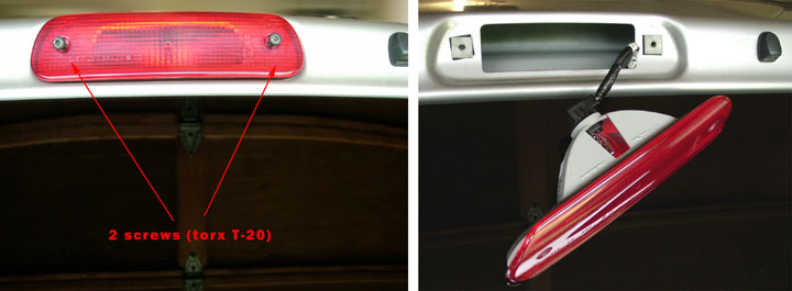
Rear: high mount stop light (# 921)
The lens housing for the high mount stop light is attached with two T-20 torx head screws. Turn the lamp socket 1/4 turn counter-clockwise to access and remove the bulb.
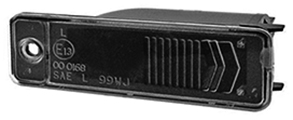
Rear: License plate light (# 168)
To replace the single bulb, remove the small Phillips head screw on the left side of the lens. Pivot the left side of the assembly from the rear cargo door about half an inch or an inch, taking care not to damage the attached wires. Grasp the soft rubber subassembly to which the wires are attached, and twist 1/4 turn counterclockwise. Pull the subassembly from the housing. Pull the old bulb straight out from the holder, dance a little dance, and insert the new bulb into the bulb holder. Assembly and installation is the reverse of disassembly and removal.
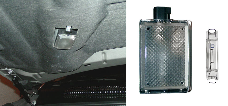
Underhood (# 561)
The plastic lens cover of the hood lamp can be easily snapped off using a tiny flat screwdriver. It is held in place with plastic clips in each corner.
This extremely handy feature was eliminated starting with the 2002 model year. The bright light was conveniently mounted over the dipsticks, lighting the entire engine area. It works with a gravity-type switch that turns the light on and off when the hood is opened and closed.
2002-2004 owners can easily install the original factory hood lamp. The screw hole and mounting tab are still present, hidden under the hood insulation cover. A rectangular piece needs to be cut out where the mounting holes are. Wiring must be run as well. A fused hot lead can be run directly to the battery or under-hood fuse box, or fed across the hood (under the insulation) and through the firewall to the inside dash. The ground wire can be run almost anywhere.
It’s probably possible to tie into the interior light system for the benefit of having the automatic 8-minute battery protection off timer, I have not been able to confirm yet how this can be done, as that would be ideal. Otherwise, a manual on-off switch can easily be added during times when you don’t want the light to stay on, as when leaving the hood open for extended periods.
The lamp-end electrical connector plug is not available separately, so one must either purchase the harness or devise a way to connect the wiring to the 2 lamp socket pins. Wires can be soldered directly on, or attached to the correct size push-on connector ends.
Another alternative (better but more expensive) is to purchase the factory wiring harness. This will allow a direct connection at the lamp end, but it must still be manually attached to the battery or + connection and ground as vehicles produced without the hood lamp do not have a factory wired receptacle available for the harness.
| Part name: “Lamp” (with housing, bulb & lens) | Part number: 56021441 | List price: $26.85 |
| Part name: “Lens” | Part number: 4897446AA | List price: $ 5.75 |
| Part name: “Harness“ | Part number: 56042574AC | List price: $30.95 |
| Part name: “Screw” (tapping, .25-14x.625) | Part number: N/A |