
Welcome to the JeepSpecs.com in-depth page on the WK Generation Jeep Grand Cherokee rear park assist system. Did we miss anything? Please get in touch with us and tell us about it!
The Rear Park Assist System provides visual and audible indications of the distance between the rear fascia and the detected obstacle when backing up. Refer to the Warning Section and Note Section for limitations of this system and recommendations.
The Rear Park Assist System will remember the last system state (enabled or disabled) from the last ignition cycle when the ignition is changed to the RUN/ON position.
The Rear Park Assist System can be active only when the shifter is in R (Reverse). If the Rear Park Assist System is enabled at this shifter position, the system will be active until the vehicle speed is increased to approximately 11.2 miles/hr (18 km/h) or above. The system will be active again if the vehicle speed is decreased to speeds less than E approximately 9.94 miles/hr (16 km/h).
Rear Park Assist Sensors
The four Rear Park Assist Sensors, located in the rear fascia, monitor the area behind the vehicle that is within the sensors’ field of view. The monitored area seems oval in shape.
The sensors can detect obstacles from approximately 11.8 inches (30 cm) up to 59 inches (150 cm) from the rear fascia in the horizontal direction, depending on the location and orientation of the obstacle and the type of obstacle.
Rear Park Assist Warning Display
The Rear Park Assist Warning Display, located in the headliner near the flipper glass, provides both visual and audible warnings to indicate the distance between the rear fascia and the detected obstacle.
When the ignition is changed to the RUN/ON position, the warning display will turn ON all of its LEDs for about I sec.
Each side of the warning display has 6 yellow and 2 red LEDs. The vehicle is close to the obstacle when the red LED is ON.
When the obstacle is detected at a distance of about 59 inches (150 cm) from the rear fascia, the outermost LEDs of the warning display will be ON with increased brightness. As the distance of the detected obstacle to the rear fascia decreases, more LEDs are illuminated. The warning display will not actuate a tone when only yellow LEDs are ON.
When the warning display has the first 7 LEDs ON, including 1 red LED, the warning display will actuate an intermittent tone for about 3 sec. The radio will be muted while the tone is actuated.
When the detected obstacle is about 11.8 inches (30 cm) from the rear fascia, the warning display will actuate a continuous tone for about 3 sec and it will turn ON all 8 LEDs, including both RED LEDs, on the corresponding side of the display. The radio will be muted while the tone is actuated.
When the obstacle is less than 11.8 inches (30 cm) from the rear fascia, the warning display will either have all 8 LEDs ON (obstacle detected) or it will have only the outermost LEDs ON with decreased brightness (obstacle not detected), depending on the location of the obstacle.
Enable/Disable the Rear Park Assist System
The Rear Park Assist System can be enabled and disabled with a switch located in the switch bank of the instrument panel.
When the switch is pressed to disable the system, the instrument cluster will display the “PARK ASSIST DISABLED” message. When the shifter is changed to R (Reverse) and the system is disabled, the instrument cluster will actuate a single chime, once per ignition cycle, and it will display the message.
The Rear Park Assist Switch LED will be ON when the Rear Park Assist System is disabled or defective. The Rear Park Assist Switch LED will be OFF when the system is enabled.
Service the Rear Park Assist System
When the Rear Park Assist System is defective, the instrument cluster will actuate a single chime, once per ignition cycle, and it will display the “SERVICE PARK ASSIST SYSTEM” message.
Cleaning the Rear Park Assist System
Clean the Rear Park Assist Sensors with water, car wash soap and a soft cloth. Do not use rough or hard cloths. Do not scratch or poke the sensors. Otherwise, you could damage the sensors.
NOTE: Clean all four Rear Park Assist Sensors regularly, taking care not to scratch or damage them. The sensors must not be covered with ice, snow, slush, mud, dirt or debris. Failure to do so can result in the system not working properly. The system might not detect an obstacle behind the fascia or it could provide a false indication that an obstacle is behind the fascia.
Assure objects are not within 11.8 inches (30 cm) from the rear fascia while driving the vehicle. Failure to do so can result in the system misinterpreting a close object as a sensor problem, causing the “SERVICE PARK ASSIST SYSTEM” message to be displayed in the instrument cluster.
Ultrasonic noise from airbrakes of nearby trucks, air powered jackhammers and air powered shop tools, to name a few, will cause the Rear Park Assist System to be disabled until the ultrasonic noise is no longer present.
CAUTION! The Rear Park Assist System is only a parking aid and it is unable to recognize every obstacle, including small obstacles. Parking curbs might be temporarily detected or not detected at all. Obstacles located above or below the sensors will not be detected when they are in close proximity.
The vehicle must be driven slowly when using the Rear Park Assist System to be able to stop in time when the obstacle is detected. It is recommended that the driver looks over his/her shoulder when using the Rear Park Assist System.
WARNING! Drivers must be careful when backing up even when using the Rear Park Assist System. Always check carefully behind your vehicle, look behind you, and be sure to check for pedestrians, animals, other vehicles, obstructions, and blind spots before backing up. You are responsible for safety and must continue to pay attention to your surroundings. Failure to do so can result in serious injury or death.
Before using the Rear Park Assist System, it is strongly recommended that the ball mount and hitch ball assembly is disconnected from the vehicle when the vehicle is not used for towing. Failure to do so can result in injury or damage to vehicles or obstacles because the hitch ball will be much closer to the obstacle than the rear fascia when the warning display turns the red LEDs ON. Also, the sensors could detect the ball mount and hitch ball assembly, depending on its size and shape, giving a false indication that an obstacle is behind the vehicle.
Reverse Sense kit for 2005-2010 Grand CherokeesReverse Sense kit for 2005-2010 Grand Cherokees
| Grand Cherokee WK Reverse Sensing System parts | ||
| Item | Part # | MSRP |
| Mopar Reverse Sensing System kit (same parts as factory install) | 82208246AF | $341.00 |
| Hole saw tool set(24mm and 30mm holesaws for sensors and display installation) | 82208882 | $21.75 |
| Hole saw tool(19mm holesaw for wire loom feed. 3/4″ holesaw will also work) | N/A from Mopar | |
(Prices listed are for reference purposes only and may vary by dealer. MSRP prices are current as of March 2013. Parts are not available from this web site.)
Installation notes
The installation notes shown below are also printed in the available PDF installation manual (link below). They are reprinted here for convenience and to give anyone interesting in buying this system an idea of what is involved for the installation. Tools required are shown below on the scan of page one of the manual.
Although not a particularly difficult installation, it is best left for professionals or those who have experience in this type of automotive work. Installation involves removing interior trim panels, removing the rear fascia, drilling holes, and soldering a couple of wires to the taillamp harness. It is highly suggested to puchase the Mopar holesaws as being metric they may be hard to find at the local hardware store.
1. Open the liftgate and remove the upper liftgate trim panel.
2. Remove the right (passenger’s side) D-pillar trim panel.
3. Install audio/visual display to the right D-pillar trim panel as shown.
4. Remove the lower liftgate trim panel.
5. Remove the right C-pillar trim panel.
6.Remove the right inner quarter trim panel.
7. Remove the rear fascia and place it on a protected surface.
8. If painting the sensors to match the vehicle color is desired by the customer, refer to the following four steps:
Step 1: Prep surface following standard paint shop procedures for painting of plastic components.
Step 2: Mix Sikkens Brand Autobase with Diluent 1:1.
Step 3: Fog-spray 1 coat of Autobase mixture. Wait 5 minutes. Wet-spray another coat of Autobase mixture. Let dry for 25 minutes.
Step 4: While Autobase is still wet, spray 1 coat of Autoclear (Varnish/Curing Agent/Diluent = 5:2 0:15). Let dry for 15 minutes. Place sensors in heated drying chamber for 60 minutes at 52°c.
9. Install sensors as shown and fully engage the clips. Attach the sensor cables.
10. Remove the right taillamp. Remove sealer patch from lower access hole in the taillamp opening panel.
11. Drill an access hole in the right inner quarter panel as shown.
12. Trim the rear fascia support in two places to allow clearance for the inboard sensor assemblies.
13. Re-install rear fascia while carefully pulling the sensor cable connectors one at a time into the vehicle. Keep cables away from sharp edges and ensure they are not pinched under the fascia. Replace any damaged plastic pop rivets from stock.
14. Route power harness wires through the drilled access hole and out of the taillamp opening access hole.
15. Determine which taillamp wires have the ground and back-up lamp signals. Disconnect the negative battery cable and perform center splicing as shown.
16. Use RTV sealant on any altered grommets to prevent water leaks.
17. Make all connections to the controller. Install controller using hook and loop patches.
12. Loop up slack in cables and wires. Apply tie straps and tape and stow away neatly. Do not kink or tightly coil the cables.
18. Re-install sealer patch to the taillamp access hole.
19. Use foam tape around cables and wires at both access holes to prevent leaks.
20. Connect audio/visual display cable to the extension cable.
21. Re-connect battery and check operation of the reverse sensing system.
22. The audio/visual display can be set to NO AUDIO, LOW AUDIO, or HIGH AUDIO.
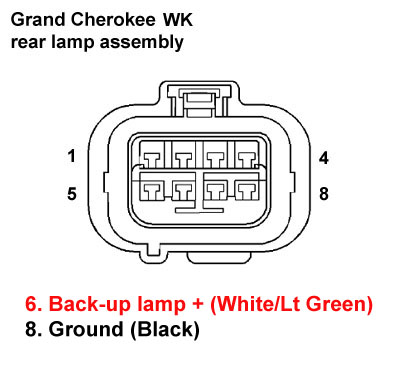
Installation step #15 above requires splicing into two rear lamp harness wires
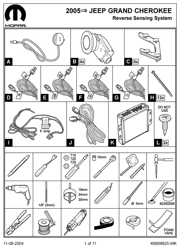
Front page scan of the Mopar installation manual