
Welcome to the JeepSpecs.com in-depth page on the WK Generation Jeep Grand Cherokee interior trim & audio component removal. Did we miss anything? Please get in touch with us and tell us about it!
1. Radio bezel and radio (2005-2007)
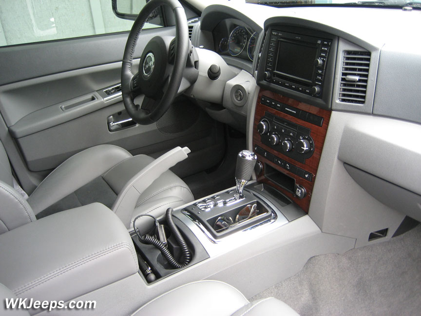
Radio bezel and center vent assembly (2005-2007)
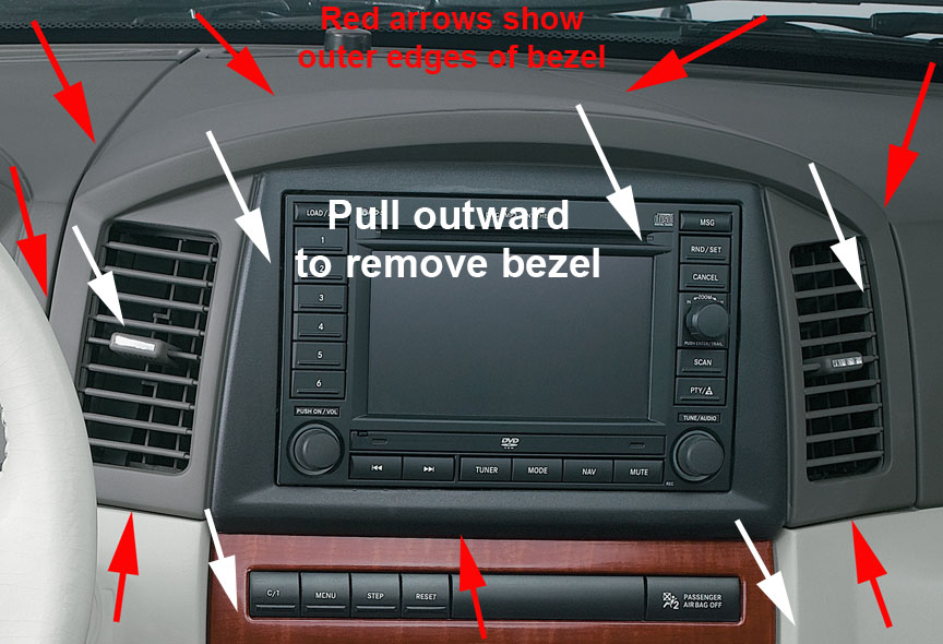
Radio bezel removal (2005-2007)
The one-piece radio/vent bezel is fastened with 5 spring clips and aligned at the top with plastic tabs. Grab the bezel in the back curved area and pull it forward to pull it away from the plastic tabs. Carefully pull the bezel outwards around its perimeter to release it from the spring tabs.
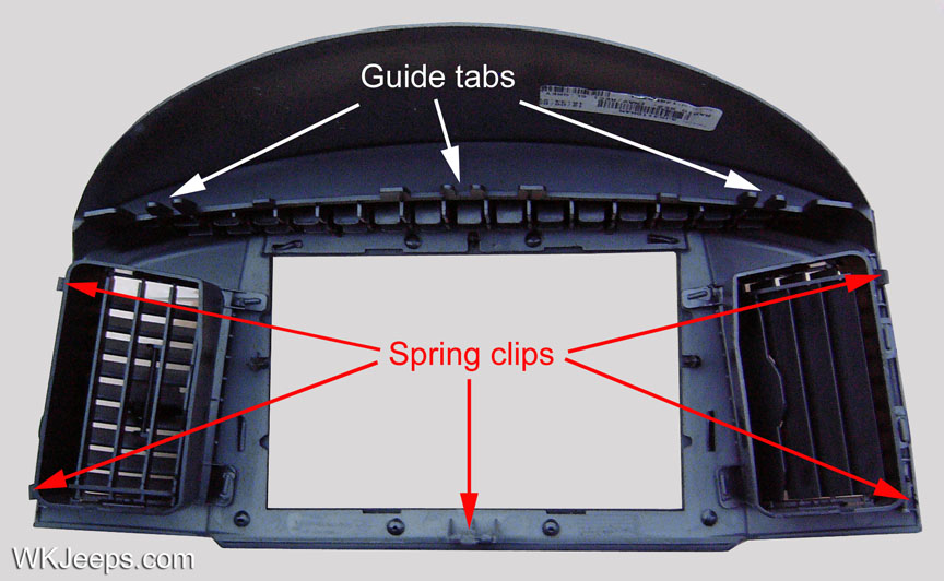
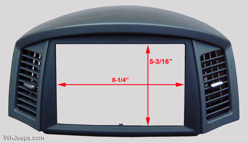
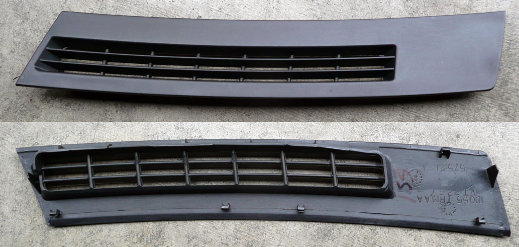
Front and back views of the navigation radio bezel (2005-2007)
Radio removal (2005-2007)
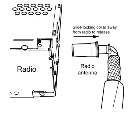
The radio is fastened with four screws, remove them and carefully pull the radio out enough to access the rear connectors. It is important to note that the radio antenna connector is the newer “locking” style”. Grasp the outer ring and pull outward to release the antenna from the radio. For reinstallation it simply pushes back on and locks in place.
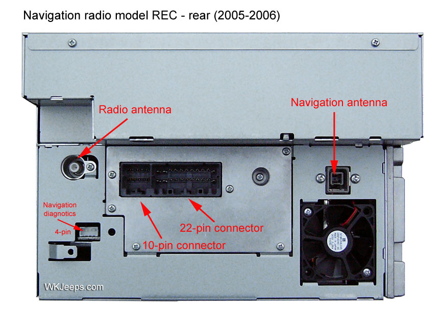
Rear radio connectors 2005-2007 Locking antenna
Radio antenna removal and installation (PDF)
2. Center stack bezel (2005-2007)
1. Remove shifter trim bezels as shown in section 3 below. Remove the phillips screw inside the cubby hole that is between the two power outlets. Once the screw is removed you can pull the entire center bezel trim piece off by hand, it is held in place with spring clips. Move the shifter to “D” for a little more room.
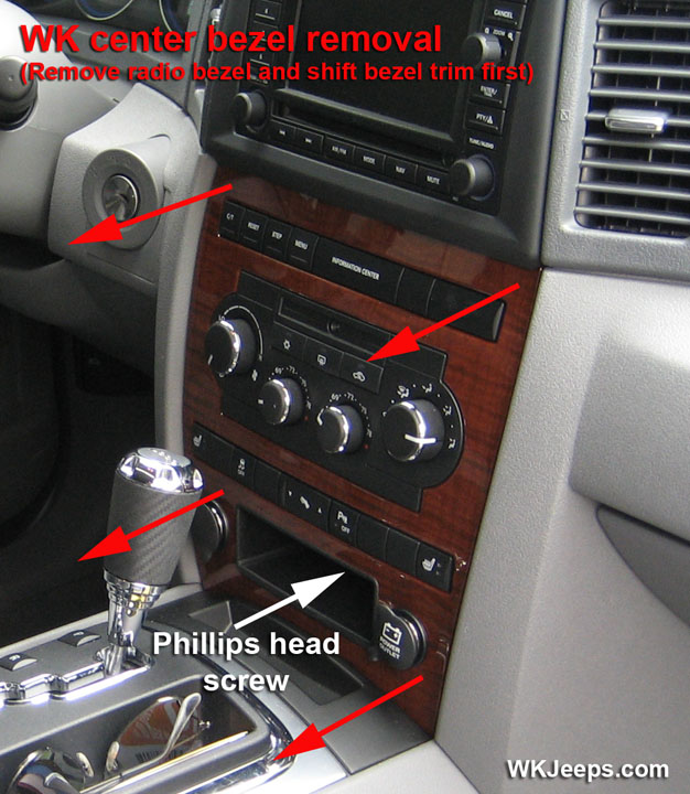
The center bezel is attached with spring clips and one phillips screw
3. Radio and Center stack bezel (2008-2010)
For 2008, the redesigned instrument panel features a one-piece radio bezel/center stack bezel. The two center air vents are also attached to the bezel, along with the switch banks and A/C controls. The entire assembly is removed as one piece.
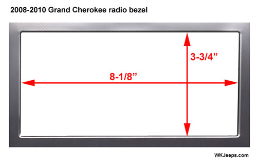
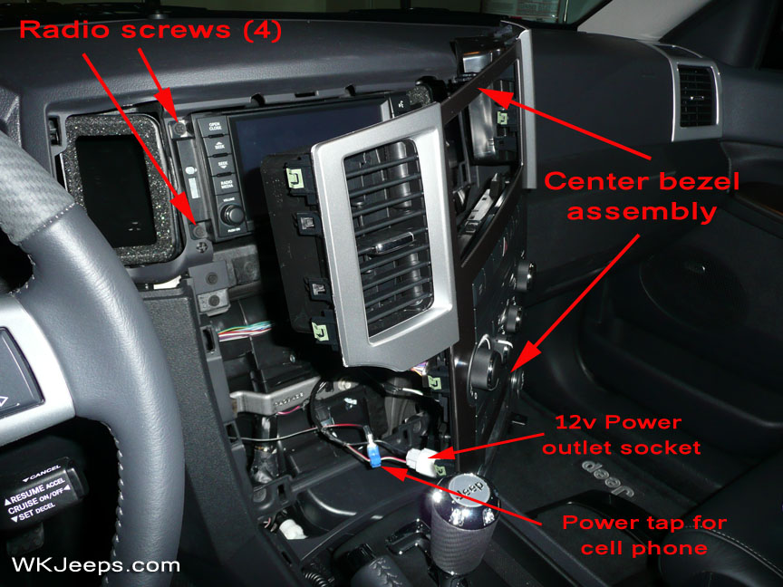
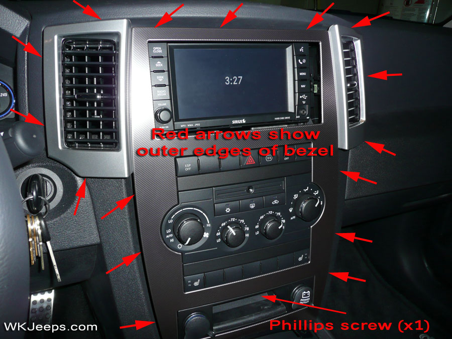
Center bezel assembly (2008-2010)
1. The shifter trim must be removed in order to remove the center bezel (see “Shifter trim” section below).
2. Remove the phillips screw located at the bottom of the center stack, inside the cubby hole.
3. With a trim stick, carefully pry around the entire perimeter of the bezel assembly, including the two air vents. Start at the bottom where there are two protruding tabs with holes in them. Place the end of a round screwdriver through the holes, using it to pull the bottom of the bezel outward on each side. You can then start to work your way upwards and evenly side to side. The center bezel is secured very tight and requires a bit of patience as you slowly free it from the spring tabs. At the top of the bezel make sure to free the vents as they are part of the bezel assembly. There is also a tab behind the bottom center of the radio which can be pulled out a little with your fingers. Before the center bezel is totally free, place a towel over the shifter area so as to not scratch the shift bezel when the center bezel is removed.
4. Once free, the center bezel can be pulled out far enough to reach behind it to unfasten the wiring harnesses for the switch banks, A/C controls and power outlets. However, it is not necessary to unplug the center stack wiring harnesses in order to access/remove the radio. With the shifter pulled back, the center bezel assembly can be rotated sideways and rested on the shift console with all wiring connectors left in place. This can also be handy when you want to tap into the back of the power outlet wiring for devices such as cell phones and radar detectors (see photo above right). Note that the left power outlet is powered on and off with the ignition, and the right outlet is powered on at all times.
Radio removal (2008-2010)
The radio is fastened with four screws, remove them and carefully pull the radio out enough to access the rear connectors. Remove the wiring harnesses and antenna connectors. It is important to note that the radio antenna connector is the newer “locking” style” (see illustration above). Grasp the outer ring and pull outward to release the antenna from the radio. For reinstallation it simply pushes back on and locks in place.
Radio antenna removal and installation (PDF)
4. Shifter trim bezels (2005-2010)
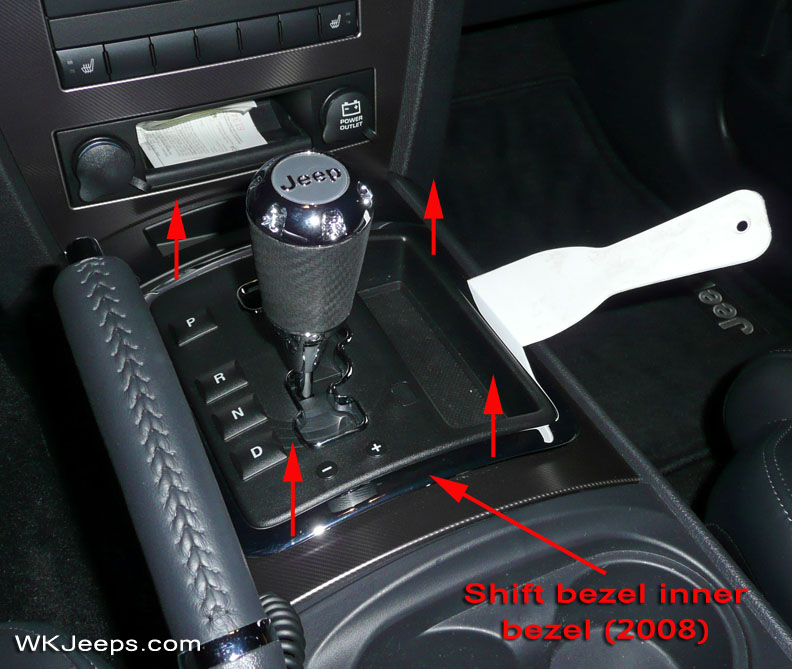

Shift bezel inner trim Shift bezel outer trim
1. Remove the chrome inner trim piece first by gently prying it up with a trim stick. Once started, the piece can be lifted up with your fingers, slowly moving around the perimeter of the trim piece. The larger outer trim, which contains the small storage pocket, is removed the same way.
5. Center floor console 2005-2010
Center console back cover Center console assembly
1. Remove the shifter trim bezels (see section 3 above).
2. Remove the center console rear cover by prying it outwards. It is held in place by springclips. Disconnect the electrical connector(s).
3. Remove the 2 screws at the bottom rear of the console.
4. Remove the cup holder mat and the phillips screw underneath it.
5. Apply Parking Brake if not already applied. Move shift lever to Drive.
6. Remove the console by lifting the back up and pulling console toward rear of vehicle.
6. Door trim panels, door speakers, window switch bezels 2005-2010
Front doors
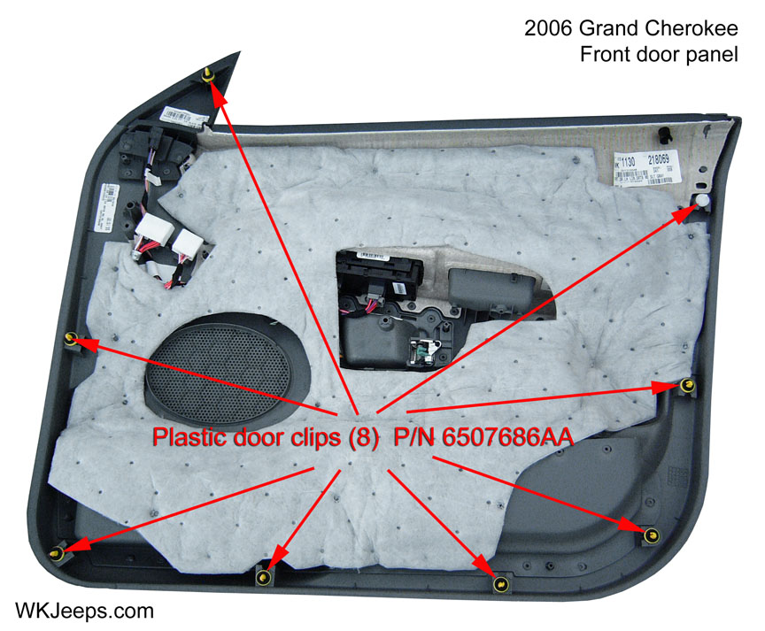

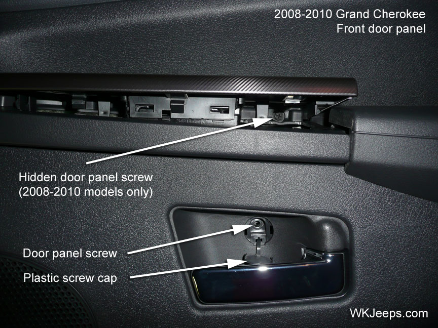
Interior door panel, front. Far right photo, hidden 3rd screw on 2008 models.
NOTE: According to the factory service manual the door panel retention clips are designed to be used only once. The eight retention clips should be discarded and replaced with new clips each time the door trim panel is removed from the door. Failure to replace retention clips may result in poor door panel retention. We have found that the panel can be removed several times and reinstalled with no problems. However, it’s always a good idea to have a few spare retention clips handy should any of them break. The part number for the front and rear door clips is 6507686AA and they can be ordered Here.
1. Disconnect and isolate the battery negative cable.
2. Remove the three phillips head screws that secure the front door trim panel to the door. The screw in the door pull is located underneath the rubber pad. The rubber pad can simple be lifted up to remove (Note: rubber pads were deleted during the 2006 model year).
2008 models important note: The 2008 front door trim panels do not have a screw located in the door pull area. Instead, this third screw is located behind the door switch trim bezel (see far right photo above). To remove the switch bezel trim, lift up around the edges with a trim stick or your fingers. Lift the bezel up just enough to free it from the armrest. You can then access the screw by placing a screwdriver between the armrest and switch bezel assembly. The drivers side is more difficult as the switch bezel also contains the mirror switch and wiring harness which leaves little room to raise the bezel enough to reach the screw.
3. Starting on the side closest to the front of the car, grab and pull the lower storage pocket outward with a jerking motion to disengage the trim panel corner from the door. If the trim panel does not easily come free use a trim stick to pry the panel away from the door in a lower corner. Once the corner is loose you can work around the sides and bottom to disengage the rest of the plastic clips by pulling the panel outward.
4. Once the two sides and bottom of the panel are free from the door, lift the door panel upward slightly, lifting it to clear the interior door lock stem and to clear the window channel opening. The door panel should now be free enough to pull it several inches away from the door.
5. While holding the front door trim panel in place a few inches away from the door, reach behind it to access and disconnect the door wire harness connectors and the interior door handle actuator rod.
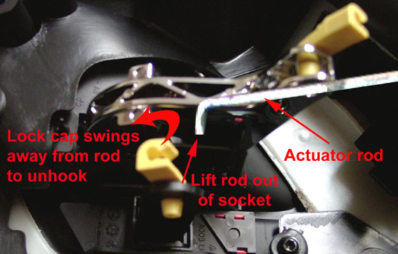
Door lock actuator rod
6. Disconnect the interior door handle actuator rod from the interior door handle (see photo above). The plastic lock tab swings away from the rod to release it, the rod can then be lifted out of its mounting socket. A narrow flat head screwdriver can be used to pry the plastic lock tab from its position.
7. Disconnect the two wire harness connectors from the power door switch assembly. Disconnect the power mirror wire harness connector if equipped. The electrical connectors have a tab that is pushed in to release it while the connector is pilled outward. The door panel can now be removed.
8. The door is covered with a black plastic cover. The cover is attached with a bead of putty and can be easily removed by slowly pulling it outward away from the door. If possible, leave as much of the putty as possible attached to the door frame by working it back to the door with your fingers. When reinstalling the cover keep it as tight as possible and be sure to line up the indentations/holes. Once in place take a rag and rub hard around the perimeter of the cover where the putty bead lies underneath. This will reseal it to the door.
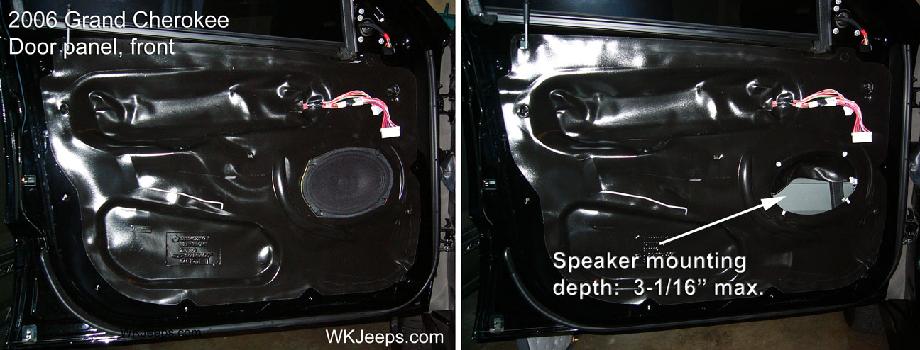
Front door shown with trim panel removed. Maxiumum speaker mounting depth is 3-1/16″
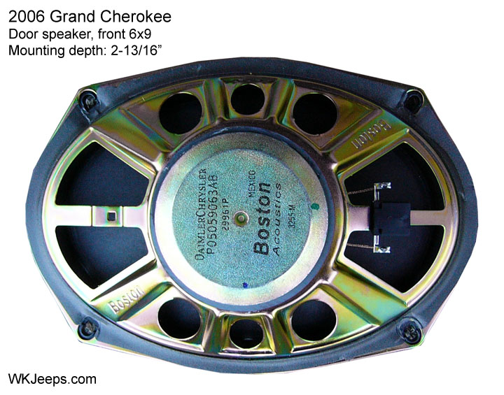
Boston Acoustics 6″x9″ front door speaker
Reinstalling the front panel
1. Hold the door panel in place and reach behind it to reconnect the electrical connectors and actuator rod. Make sure all connectors are pushed in tight.
2. Align the top corner of the panel through the door lock stem. Fit the top edge of the panel into the window rail where it should hook over and sit flush.
3. Align the plastic fastener that is behind the mirror area into its hole and push firmly. You can now work around the door panel to push in the rest of the fasteners. Check the entire perimeter of the door panel to make sure it is flush with the door.
4. Reconnect the negative ground cable.
Rear doors
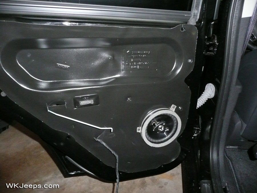
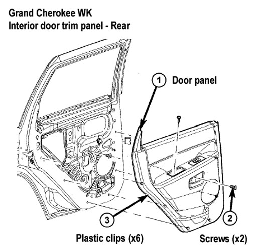
Interior door panel, rear
NOTE: According to the factory service manual the door panel retention clips are designed to be used only once. The eight retention clips should be discarded and replaced with new clips each time the door trim panel is removed from the door. Failure to replace retention clips may result in poor door panel retention. We have found that the panel can be removed several times and reinstalled with no problems. However, it’s always a good idea to have a few spare retention clips handy should any of them break. The part number for the front and rear door clips is 6507686AA and they can be ordered Here.
1. Disconnect and isolate the battery negative cable.
2. Remove the two phillips screws that secure the rear door trim panel to the door.
3. Grab and pull the lower storage pocket outward with a jerking motion to disengage the trim panel corner from the door. Once the corner is loose you can work around the sides and bottom to disengage the rest of the plastic clips by pulling the panel outward.
4. Once the two sides and bottom of the panel are free from the door, lift the door panel upward slightly, lifting it to clear the interior door lock stem. The door panel should now be free enough to pull it several inches away from the door.
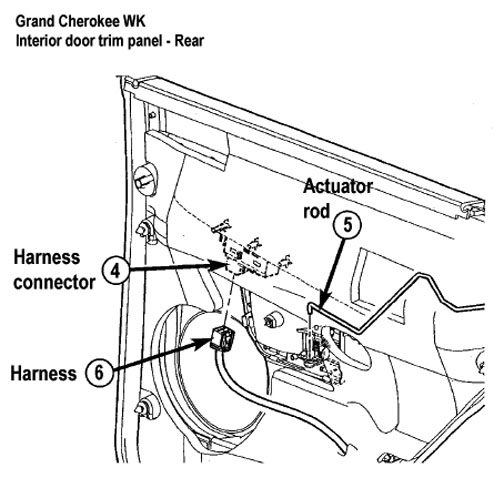
5. Position the rear door trim panel far enough away to access the door panel wire harness connector and the interior door handle actuator rod.
6. Disconnect the interior door handle actuator rod from the interior door handle (see photo of front door above). The plastic lock tab swings away from the rod to release it, the rod can then be lifted out of its mounting socket. A narrow flat head screwdriver can be used to pry the plastic lock tab from its position.
7. Disconnect the wire harness connector from the power door switch assembly. The electrical connector has a tab that is pushed in to release it while the connector is pulled outward. The door panel can now be removed.
8. The door is covered with a black plastic cover. The cover is attached with a bead of putty and can be easily removed by slowly pulling it outward away from the door. If possible, leave as much of the putty as possible attached to the door frame by working it back to the door with your fingers. When reinstalling the cover keep it as tight as possible and be sure to line up the indentations/holes. Once in place take a rag and rub hard around the perimeter of the cover where the putty bead lies underneath. This will reseal it to the door.
Reinstalling the rear panel
1. Hold the door panel in place and reach behind it to reconnect the electrical connector and actuator rod. Make sure connector is pushed in tight.
2. Align the top corner of the panel through the door lock stem. Fit the top edge of the panel into the window rail where it should hook over and sit flush.
3. Work around the door panel to push in place each of the six trim panel fasteners. Check the entire perimeter of the door panel to make sure it is flush with the door.
4. Reconnect the negative ground cable.
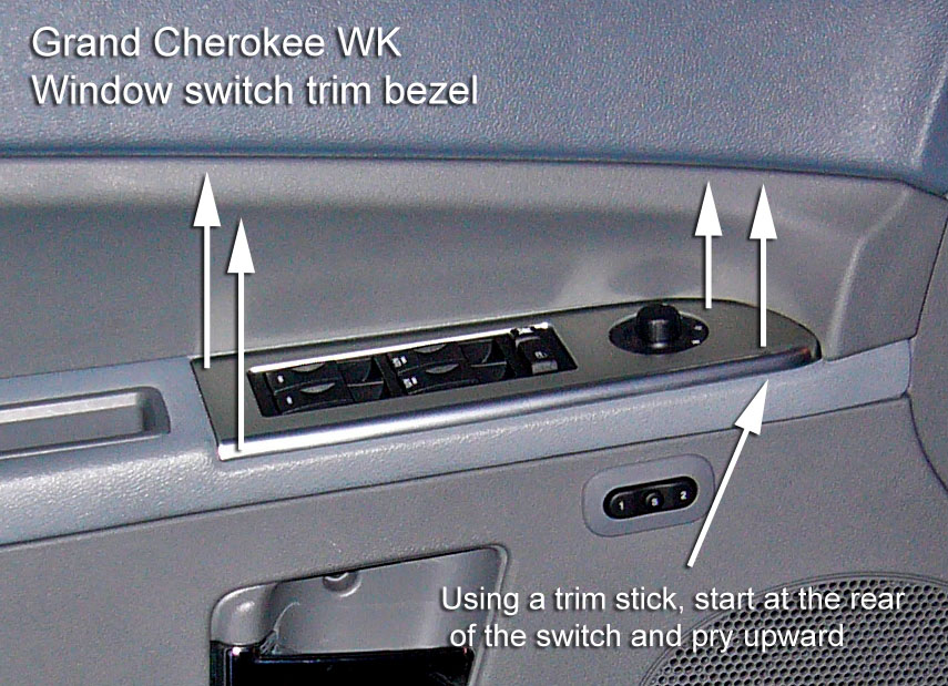
Window switch bezel trim (front and rear doors)
Removal
1. Disconnect and isolate the battery negative cable.
2. Using a trim stick, start at the rear of the switch housing (1) and pry up to remove from door trim panel.
3. Disconnect electrical harness connectors from switch.
4. Remove switch from housing.
Installation
1. Position switch into place in the housing and push down until it snaps into place.
2. Connect electrical connectors to switch.
3. Insert front end of switch housing into door trim panel opening. Press into place.
4. Connect negative battery cable.
7. Instrument panel speakers / A-pillar grab handles 2005-2010
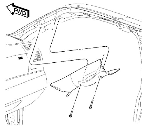
Intrument panel speakers A-pillar grab handles
1. The grab handle/A-pillar trim must be removed to access the speaker grilles. The handles are removed by prying open the plastic bolt covers with a small flat screwdriver and then removing the two bolts with a small diameter 10mm socket. The grilles are attached quite firmly, with 5 tangs holding them in place. Remove the speaker screws with a short 90-degree phillips screwdriver or socket wrench.
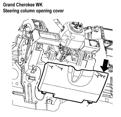
8. Steering column access door and hush panel 2005-2010
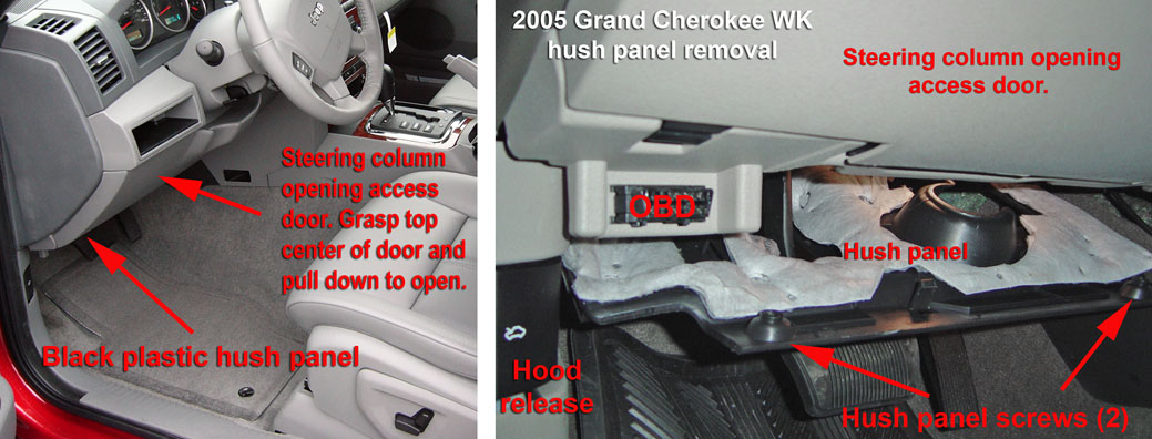
WK hush panel
1. The lower hush panel is attached with two screws, remove the screws and lower the panel downward a little to pull it out. NOTE: This panel does not have to be removed in order to open the steering column opening cover that is above it.
WK hush panel
2. The steering column access door is hinged at the bottom and secured shut with spring clips at the top. Pull the top edge away from the dash and pull downward to open.
9. Liftgate trim panel and exterior handle 2005-2010
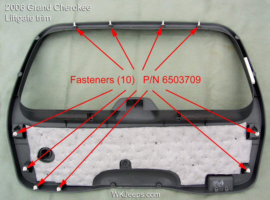
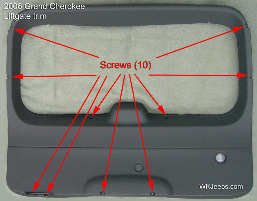
The liftgate trim panel is attached with 10 screws and 10 plastic fasteners
1. Remove the 8 short phillips head screws located around the perimeter of the liftgate trim panel and the two long screws that are near the glass lock actuator.
2. With a trim tool or flat plastic putty knife pry up the trim on the side closest to the interior tailgate light. There are 10 plastic fasteners that hold the trim in place. Work around the liftgate trim to carefully separate it from the door. Before the trim can be completely removed you must disconnect the electrical connector from the tailgate light.
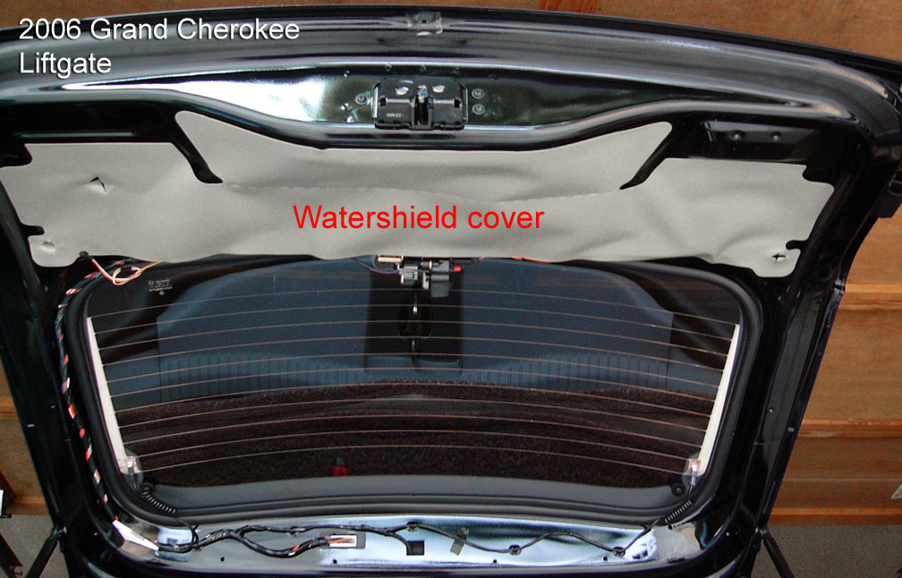
View of inside liftgate with trim panel removed.
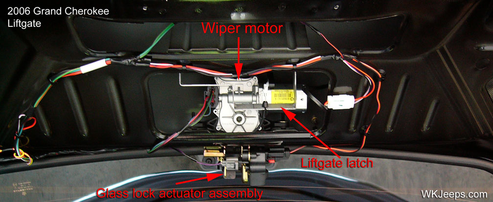
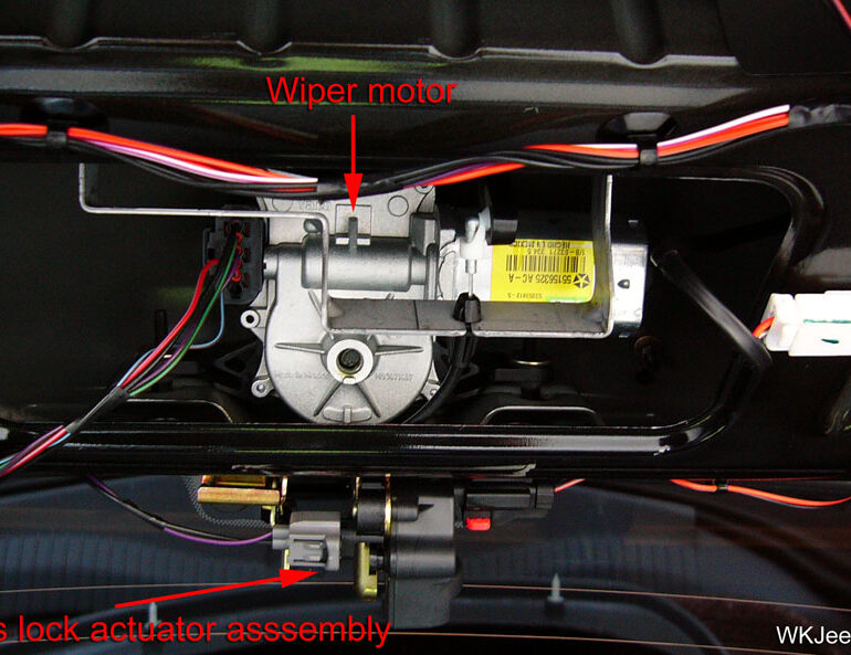
Inside of liftgate showing wiper motor and lock components
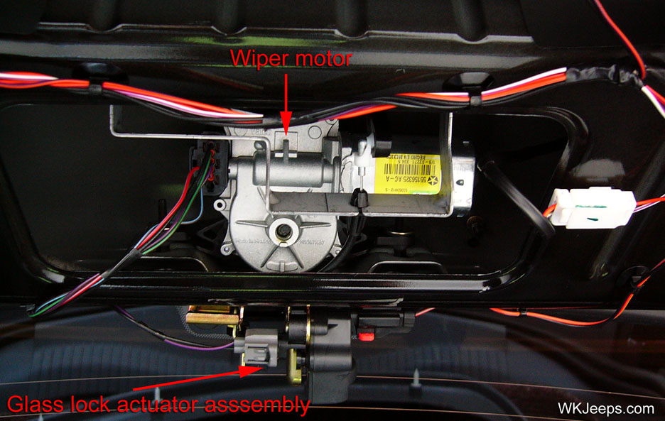
Closeup view of wiper motor and lock components
Liftgate handle removal
1. Disconnect and isolate the battery negative cable.
2. Remove the trim panel from the inside of the liftgate as shown above.
3. Remove the liftgate watershield.
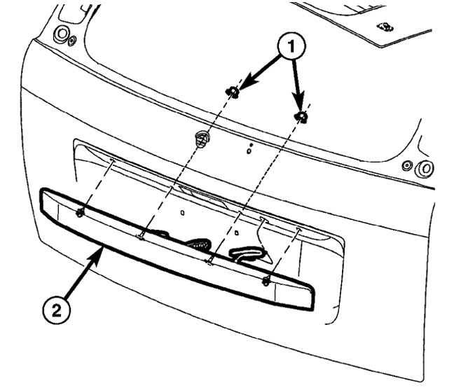
4. Disconnect the electrical connector of the latch handle (2) on the inside of the liftgate.
5. Disconnect actuator cable from latch handle.
6. Reach through the clearance hole in the inside of the liftgate panel on each side of the latch to access and remove the two nuts (1) that secure the handle to the liftgate.
7. Reach through the clearance hole on the inside of the liftgate, squeeze clips and remove the latch handle.
Liftgate handle
10. Cowl trim and door sill scuff plates 2005-2010
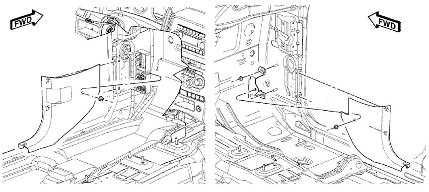
Cowl trim
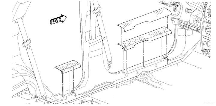
Door sill scuff plates
Removal
1. Remove the front door sill scuff plate by using a trim stick or lifting up by hand, to disengage the retaining tabs that secure the door sill scuff plate to the retaining clips in the door sill.
2. Remove the hush panel from underneath the instrument panel (see section 8 above).
3. Remove the nut that secures the cowl trim panel to the mounting bracket.
4. Remove the cowl trim panel.
Installation
1. Align the fastener hole in the cowl trim panel with the stud on the mounting bracket and then seat the trim panel onto the mounting bracket.
2. Install the nut that secures the cowl trim panel to the mounting bracket.
3. Install the hush panel.
4. Install the front door sill scuff plate by aligning the retaining tabs on the door sill scuff plate with the retaining clips in the door sill and firmly pushing downward.
11.Rear quarter panel trim, rear load floor & audio amplifier 2005-2010
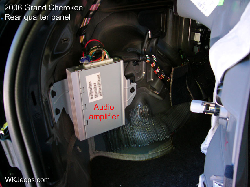
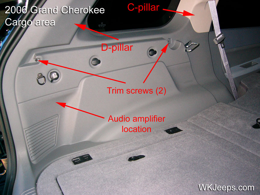
The audio amplifier is located behind the drivers side quarter trim panel in the cargo area
1. Remove the rear passenger seat cushion. The seat cushion is attached with two bolts, one on each side of the bottom of the cushion (see item 14 below for seat cushion removal). NOTE: This step is only necessary if you plan to completely remove the quarter trim panel from the vehicle. The amplier can be accessed and removed as the trim panel can be pulled out far enough for access behind it. CAUTION: Do not pull quarter trim panel too far outwards, especially when cold, as it can crack on the narrow end.
2. Fold the rear seat down and remove any stored items from the cargo area. Remove the cargo shade if installed.
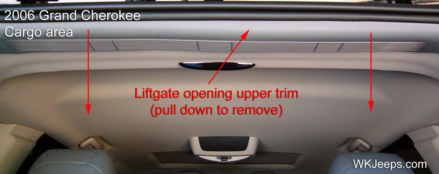
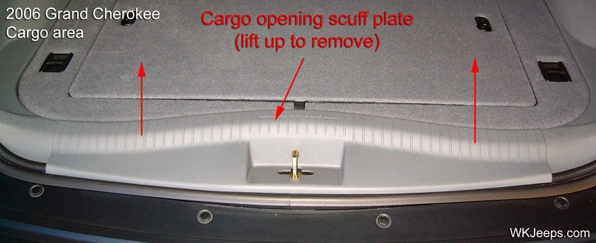
Liftgate opening scuff plate and upper trim
3. Remove the upper liftgate opening trim piece and the lower scuff plate. Both are attached with spring clips and are easily pulled off. See photos above.
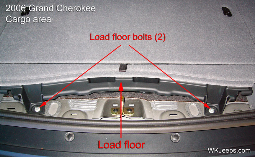
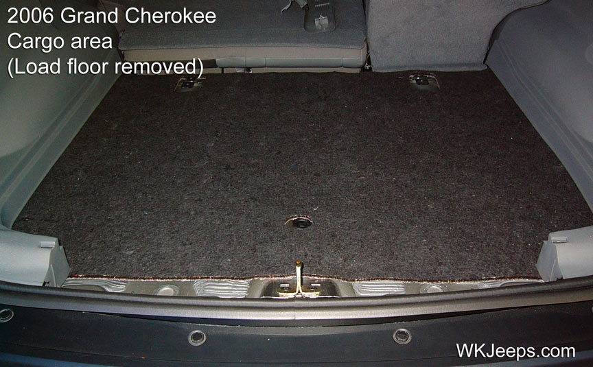
Location of load floor bolts and photo of cargo area with load floor removed
4. Remove the cargo area load floor. It is attached with two bolts as shown in the photo above. Remove the bolts with a 15mm socket and lift the load floor up and pull out to remove from the vehicle.
5. Remove the D-pillar trim. It is attached with spring clips and pulls off from the top.
6. Using a trim stick or equivalent, disengage the retaining tabs that secure the upper C-pillar trim panel to the retaining clips in the C-pillar and position the panel and the seat belt out of the way.
7. Remove the two phillips screws that secure the quarter trim panel to the quarter panel. NOTE: It is not necessary to remove the torx screw that attaches the cargo net hook to the trim panel.
8. Pull the quarter trim panel away from the quarter panel. If equipped, disconnect the 12v power outlet wire harness connector.
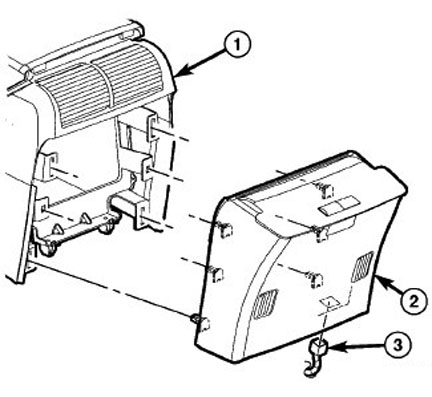
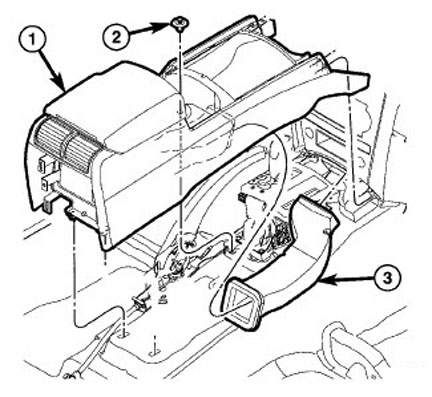
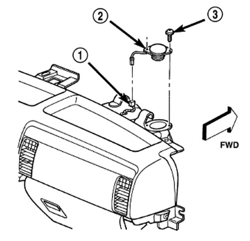
12. Glovebox 2005-2010
Glovebox removal and installation
Glovebox removal
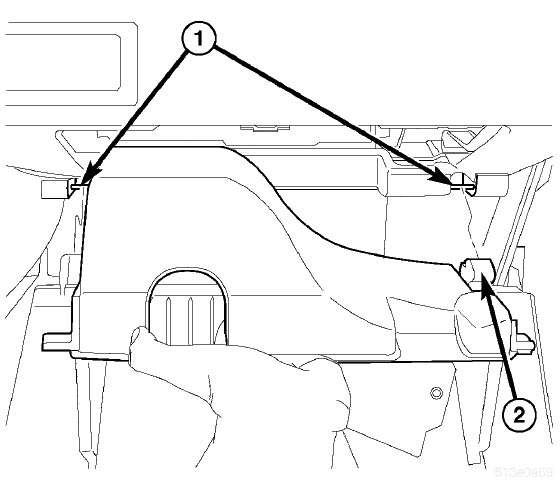
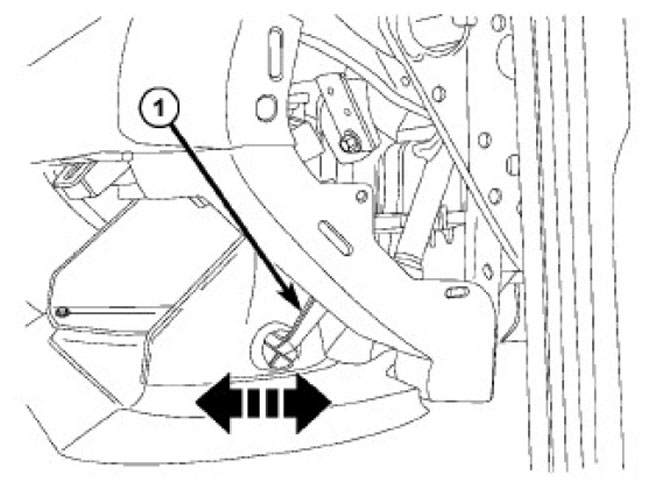
1. If equipped, separate the glove box damper rod (1) from the glove box by sliding the rod towards the rear of the vehicle to release it from the bin. Be careful not to pull on the end of the damper too hard or it may come out of its socket.
2. Open the glove box and push the stop tabs down to drop the glove box out of the instrument panel.
3. Rotate the box down and release the door hinges (2) at the bottom and remove the glove box.
Glovebox installation
1. Snap the lower glove box hinges (2) over the pivots (1) and rotate up.
2. Push the stop tabs down and close the glove box.
3. Connect the damper rod (1) to the outer side of the box compartment.
13. Cluster bezel 2005-2010
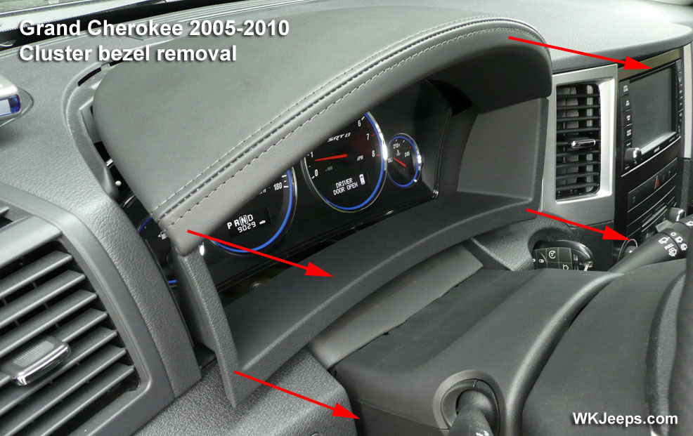
Cluster bezel removal
1. The non-leather bezel is held in place by two spring clips at the bottom, and flat plastic guide tabs at the top. The leather wrapped bezel is held in place by 5 spring clips, two on the bottom and three on the top.
2. To remove, lift from underneath the bottom left and right sides and pull the bezel forward to release it from the spring clips. For the leather bezel, the top half will require pulling forward to release three additional spring clips.
3. To install, align spring clips and tabs and push bezel straight in.
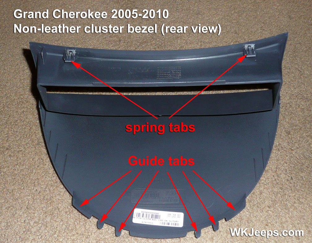
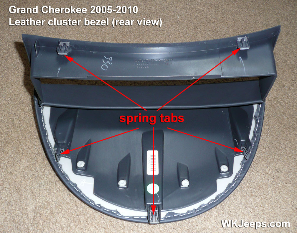
Standard cluster bezel and leather wrapped cluster bezel – rear views
14. Seat cusion and seat back, rear 2005-2010
Rear seat cushion removal
Rear seat cushion removal
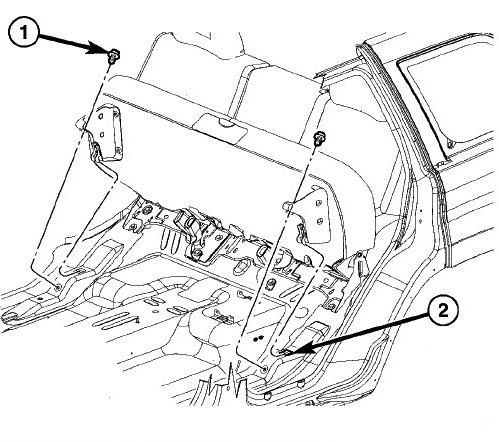
1. Remove the two mounting bolts (1), one from each side of the vehicle.
2. Slide the rear seat cushion forward to release the hooks (2) from the body pan.
Rear seat cushion installation
1. Tuck the rear of the seat cushion underneath the seat back and as you are doing so, make sure the hooks are sliding into the slots in the body (2).
2. Install the two bolts to the rear seat cushion. Tighten to 50 N·m (37 ft. lbs.).
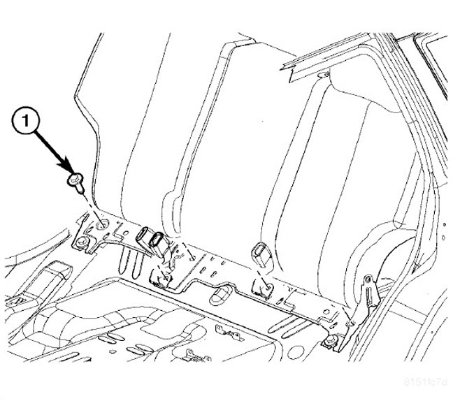
Rear seat back removal
Rear seat back removal
1. Remove the rear seat cushion.
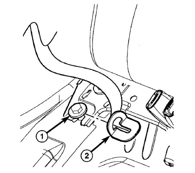
2. Loosen outboard lower anchor bolts (1) and slide the rear seat belt anchor (2) off the bolt.
3. Remove the four rear seat back mounting bolts (1) and remove seat back from vehicle.
Rear seat back installation
1. Place the rear seat back into position by slipping the hinge bracket onto the two outboard lower bolts.
2. Install the other four mounting bolts (1). Remember to install the three inner seat belt buckles. Torque the bolts to 50 N·m (37 ft. lbs.).
3. Slide the two outboard seat belt anchors (2) onto the outboard lower bolts (1). Tighten bolts to 50 N·m (37 ft. lbs.).
4. Install the rear seat cushion.
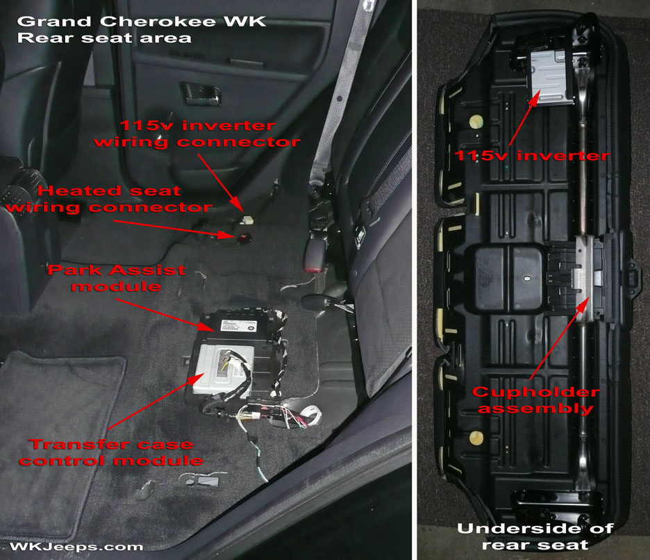
Underneath rear seat, 2008 model showing location of Parl Assist, Power Inverter and T-Case control modules.
15. Defrost vent covers 2005-2010
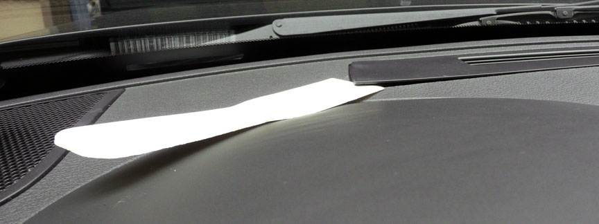
Defrost vent covers, pry up from corner to remove
Defrost vent covers removal
1. The vent covers are held in place with plastic tabs. With a trim stick or plastic putty knife, pry up one corner and lift up the vent cover to remove.
Defrost vent covers, front and back
16. Overhead console 2005-2010
Overhead console removal (PDF)