

Welcome to the JeepSpecs.com In-Depth page on the WK2 Jeep Grand Cherokee cruise control systems. Did we miss anything? get in touch with us and let us know!
1. Conventional electronic speed control system
The standard equipment conventional electronic speed control system includes the following major components:
- Antilock Brake Module – An Antilock Brake Module (ABM) (also known as Controller Antilock Brake/CAB or the Electronic Stability Control/ESC module) is located on the antilock brake Hydraulic Control Unit (HCU) in the engine compartment.
- Brake Lamp Switch – The brake (also known as stop) lamp switch is located on the brake pedal support bracket under the driver side of the instrument panel.
- ElectroMechanical Instrument Cluster – A CRUISE indicator is located in the fixed segment display of the ElectroMechanical Instrument Cluster (EMIC) (also known as the Cab Compartment Node/CCN) that provides an indication to the vehicle operator when the speed control system is turned ON.
- Powertrain Control Module – The Powertrain Control Module (PCM) in the right front corner of the engine compartment contains the software and hardware that monitors all of the speed control system inputs and controls all of the speed control system outputs.
- Speed Control Switches – A speed control switch pod containing four momentary switch push buttons is located in the right horizontal spoke of the steering wheel.
- Steering Control Module – A Steering Control Module (SCM) is integral to the Steering Column Control Module (SCCM) located at the top of the steering column just below the steering wheel.
- Wheel Speed Sensors – A wheel speed sensor is located on the knuckle of each front and rear wheel.
The ABM, the EMIC, the PCM and the SCM each contain a microprocessor and programming that allow them to communicate with each other using the Controller Area Network (CAN) data bus. This method of communication is used by the SCM to relay the status of the speed control switches to the PCM, and by the PCM for control of the CRUISE indicator in the EMIC.
Hard wired circuitry connects the conventional electronic speed control system components to the electrical system of the vehicle. These hard wired circuits are integral to several wire harnesses, which are routed throughout the vehicle and retained by many different methods. These circuits may be connected to each other, to the vehicle electrical system and to the speed control system components through the use of a combination of soldered splices, splice block connectors, and many different types of wire harness terminal connectors and insulators. Refer to the appropriate wiring information. The wiring information includes wiring diagrams, proper wire and connector repair procedures, further details on wire harness routing and retention, as well as pin-out and location views for the various wire harness connectors, splices and grounds.
Operation – conventional speed control
The vehicle operator controls all conventional speed control system features through the speed control switch pod on the face of the right horizontal spoke of the steering wheel. When a push button of the switch pod is depressed, it provides a hard wired resistor multiplexed analog input to the Steering Control Module (SCM).
The SCM reads the speed control switch input via LIN, then relays an electronic speed control switch status message to the Powertrain Control Module (PCM) over the Controller Area Network (CAN) C data bus. The PCM software continually monitors these inputs as well as electronic vehicle distance message inputs from the Antilock Brake Module (ABM) (also known as the Controller Antilock Brake/CAB, the Electronic Stability Control/ESC module or the Antilock Brake System/ABS module) and numerous hard wired inputs including the brake (or stop) lamp switch, then provides the appropriate electronic message and hard wired outputs to invoke the requested electronic speed control features.
The PCM microprocessor continuously monitors all of the speed control system electrical circuits to determine the system readiness. If the PCM detects a monitored system fault, it sets and stores a Diagnostic Trouble Code (DTC). The PCM uses On-Board Diagnostics (OBD) and can communicate with other electronic modules in the vehicle as well as with the diagnostic scan tool using the CAN data bus. This method of communication is used for control of the Malfunction Indicator Lamp (MIL) (also known as the Check Engine lamp) in the ElectroMechanical Instrument Cluster (EMIC) (also known as the Cab Compartment Node/CCN) and for system diagnosis and testing through the 16-way data link connector located on the driver side lower edge of the instrument panel.
If the ECM/PCM detects a fault on one of the following systems, it will disable the cruise control system. The ECM/PCM will store an appropriate DTC.
- Engine Speed Sensor
- Sensor or actuators of the electric throttle (only for gasoline engines)
- Accelerator Pedal Potentiometer (APP Sensor)
- Brake Pedal Position
- Clutch Switch rationality
- Engine Load sensor (only for gasoline engines)
- Ignition Coils (only for gasoline engines)
- Fuel Injectors
- High pressure system components (only for GDI and Diesel engines)
- Turbo sensors or actuators.
The hard wired inputs and outputs for the PCM may be diagnosed using conventional diagnostic tools and procedures. Refer to the appropriate wiring information. However, conventional diagnostic methods will not prove conclusive in the diagnosis of the PCM or the electronic controls or communication between other modules and devices that provide features of the conventional speed control system. The most reliable, efficient, and accurate means to diagnose the PCM or the electronic controls and communication related to speed control system operation requires the use of a diagnostic scan tool. Refer to the appropriate diagnostic information.
2. Adaptive electronic speed control system (aka Adaptive Cruise Control)
The optional equipment adaptive electronic speed control system includes the following major components:
- Adaptive Speed Control Module – An adaptive speed control sensor (also known as the Adaptive Cruise Control/ACC sensor or module and the radar sensor or module) is located on a bracket secured near the center of the underside of the front bumper support member of the Front End Module (FEM) behind the front fascia.
- Antilock Brake Module – An Antilock Brake Module (ABM) (also known as Controller Antilock Brake/CAB or the Electronic Stability Control/ESC module) is located on the antilock brake Hydraulic Control Unit (HCU) in the engine compartment.
- Brake Lamp Switch – The brake (also known as stop) lamp switch is located on the brake pedal support bracket under the driver side of the instrument panel.
- ElectroMechanical Instrument Cluster – A CRUISE indicator is located in the fixed segment display of the ElectroMechanical Instrument Cluster (EMIC) (also known as the Cab Compartment Node/CCN) that provides an indication to the vehicle operator when the speed control system is turned ON.
- Electronic Vehicle Information Center – The Electronic Vehicle Information Center (EVIC) is located in the ElectroMechanical Instrument Cluster (EMIC) (also known as the Cab Compartment Node/CCN) and provides an interface to the vehicle operator for setting the adaptive speed control customer preferences as well as a display of the adaptive speed control and Forward Collision Warning (FCW) system status messages.
- Forward Facing Camera – The Forward Facing Camera (FFC) is located inside the Combined Rear View Mirror Module (CRVMM) housing assembly. The FFC provides input for data fusion purposes allowing the ACC sensor radar data to be redundancy checked.
- Powertrain Control Module – The Powertrain Control Module (PCM) located in the right front corner of the engine compartment contains the software and hardware that monitors all of the speed control system inputs and controls all of the speed control system outputs.
- Speed Control Switches – A speed control switch pod containing six momentary switch push buttons is located in the right horizontal spoke of the steering wheel.
- Steering Control Module – A Steering Control Module (SCM) is integral to the Steering Column Control Module (SCCM) located at the top of the steering column just below the steering wheel.
- Wheel Speed Sensors – A wheel speed sensor is located on the knuckle of each front and rear wheel.
Functional Overview
The optional ACC Plus (ACC +) system (also known as ACC Stop and Go) has functionality beyond that of Normal Cruise Control and Adaptive Cruise Control. This system has the functionality of the cruise control system of maintaining a driver defined Set Speed without the driver needing to press the throttle. This system also has the functionality of the regular ACC system of increasing and decreasing the vehicle speed based on target vehicles moving slower than the ACC Set Speed. Beyond the functionality of the regular ACC system, this system offers a larger operational speed range, which constitutes of speeds from 0 mph to a configurable upper bound. If a target vehicle comes to a standstill, the ACC+ system will also bring the ACC+ host vehicle to a stop, and will keep the vehicle at a standstill for an undetermined period of time by first applying the brakes, and after the brakes time-out, cancelling the ACC+ system and applying the Electronic Park Brake (EPB). The ACC with stop and go system will also incorporate Forward Collision Warning-Plus (FCW). With grade braking, the transmission will automatically downshift to maintain selected vehicle speed and distance, preventing overheating of brakes.
The ACC sensor, the FFC, the ABM, the EMIC, the EVIC, the PCM and the SCM each contain a microprocessor and programming that allow them to communicate with each other using the Controller Area Network (CAN) data bus. This method of communication is used by the ACC module to provide inputs to the ABM, the EVIC and the PCM. This is also is used by the ABM to provide inputs to the PCM, by the SCM to relay the status of the speed control switches to the PCM and by the PCM for control of the indicators in the EMIC and the indications in the EVIC.
The ACC with stop and go system used also incorporates grade braking and Forward Collision Warning-Plus (FCW). With grade braking, the transmission will automatically downshift to maintain selected vehicle speed and distance, preventing overheating of brakes.
Hard wired circuitry connects the adaptive electronic speed control system components to the electrical system of the vehicle. These hard wired circuits are integral to several wire harnesses, which are routed throughout the vehicle and retained by many different methods. These circuits may be connected to each other, to the vehicle electrical system and to the speed control system components through the use of a combination of soldered splices, splice block connectors, and many different types of wire harness terminal connectors and insulators. Refer to the appropriate wiring information. The wiring information includes wiring diagrams, proper wire and connector repair procedures, further details on wire harness routing and retention, as well as pin-out and location views for the various wire harness connectors, splices and grounds.
Forward Facing Camera
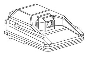
The Forward Facing Camera Module (FFC) is a stand-alone monocular camera mounted to the inside interior of the front windshield, within the Combined Rear View Mirror Module (CRVMM) housing, that captures and processes video images.
The camera performs the following functions:
- Automatic High Beam Control (AHBC) – Based on ambient situations, the AHBC feature will control the vehicle high-beam headlights automatically, relieving the driver of the manual operation of the high beam headlights. The AHBC feature automatically turns off the high beams when there is oncoming traffic, preceding traffic, presence of a village, high ambient lighting due to a town or twilight/dusk, when the vehicle driving speed to low, delay and fog.
- Object detection for supporting data fusion (ACC+) – The FFC acts as a secondary radar for the ACC system. The camera provides additional object, lane and environmental conditions for data fusion. The FFC will also perform redundancy checks with the ACC master radar to verify accurate detection.
- Forward Collision Warning Plus (FCW+) – The FFC in conjunction with the radar sensor is used to detect whether the vehicle is approaching another vehicle or large obstacle in its path too rapidly and will warn/assist the driver in avoiding/mitigating the incident (when enabled). The driver has the ability to adjust the sensitivity and turn brake support on or off in the radio.
Operation – Adaptive speed control
The vehicle operator controls all adaptive speed control system (ACC) features through the speed control switch pod on the face of the right horizontal spoke of the steering wheel. When a push button of the switch pod is depressed, it provides a hard wired resistor multiplexed analog input to the Steering Control Module (SCM).
The SCM reads the speed control switch input, then relays an electronic speed control switch status message to the Powertrain Control Module (PCM) and to the adaptive speed control sensor (also known as the Adaptive Cruise Control/ACC sensor or module, or as the radar sensor or module) over the Controller Area Network (CAN) data bus. The PCM and ACC sensor microprocessors continually monitor these inputs as well as electronic wheel speed message inputs from the Antilock Brake Module (ABM) (also known as the Controller Antilock Brake/CAB, the Electronic Stability Control/ESC module or the Antilock Brake System/ABS module), electronic gear selector message inputs from the Transmission Control Module TCM, video data from the Forward Facing Camera (FFC) and numerous hard wired inputs including the brake (or stop) lamp switch, then provides the appropriate electronic message and hard wired outputs to invoke the requested electronic speed control features.
Using the MODE push button of the speed control switch pod on the face of the right horizontal spoke of the steering wheel, the vehicle operator can choose between adaptive speed control and conventional speed control modes of operation. As the name implies, when in the conventional speed control mode the speed control system is used and functions exactly like a conventional speed control system. When in the adaptive speed control mode, the vehicle operator can use the DISTANCE push button of the speed control switch pod to select from one of three distance settings for the adaptive cruise system to maintain. These settings equate to the time in seconds separating the vehicle from a preceding vehicle. The FFC and the ACC sensor share a private bus allowing data fusion to occur within the ACC sensor. The ACC sensor then uses this information to send electronic message outputs to the ABM, the TCM and the PCM to maintain the selected separation distance.
The available distance settings are:
1 – 1.0 second
2 – 1.5 seconds
3 – 2.0 seconds
If the ECM/PCM detects a fault on one of the following systems, it will disable the cruise control system. The ECM/PCM will store an appropriate DTC.
- Engine Speed Sensor
- Sensor or actuators of the electric throttle (only for gasoline engines)
- Accelerator Pedal Potentiometer (APP Sensor)
- Brake Pedal Position
- Clutch Switch rationality
- Engine Load sensor (only for gasoline engines)
- Ignition Coils (only for gasoline engines)
- Fuel Injectors
- High pressure system components (only for GDI and Diesel engines)
- Turbo sensors or actuators.
The PCM and ACC sensor microprocessors continuously monitor all of the speed control system electrical circuits to determine the system readiness and accuracy. If the PCM or ACC sensor detects a monitored system fault, it sets and stores a Diagnostic Trouble Code (DTC). The PCM and ACC components use On-Board Diagnostics (OBD) and can communicate with other electronic modules in the vehicle as well as with the diagnostic scan tool using the CAN data bus. This method of communication is used for control of the Malfunction Indicator Lamp (MIL) (also known as the Check Engine lamp) in the ElectroMechanical Instrument Cluster (EMIC) (also known as the Cab Compartment Node/CCN) and for system diagnosis and testing through the 16-way data link connector located on the driver side lower edge of the instrument panel.
The hard wired inputs and outputs for the PCM and the ACC sensor may be diagnosed using conventional diagnostic tools and procedures. Refer to the appropriate wiring information. However, conventional diagnostic methods will not prove conclusive in the diagnosis of the PCM, the ACC sensor or the electronic controls or communication between other modules and devices that provide features of the adaptive speed control system. The most reliable, efficient, and accurate means to diagnose the PCM, the ACC sensor or the electronic controls and communication related to speed control system operation requires the use of a diagnostic scan tool. Refer to the appropriate diagnostic information.
NOTES:
- Sales code “NH1”
3. Adaptive electronic speed control system w/Stop (starting with 2014.5 model year; 2015-up model years for SRT)
(also known as Adaptive Cruise Control-Plus, Adaptive Cruise Control+, and ACC+)
Adaptive Cruise Control w/Stop is significant for its capacity to bring the vehicle to a complete stop without driver intervention in certain conditions. Radar and video sensors identify the locations of vehicles traveling ahead of the 2014 Jeep Grand Cherokee. The sensors also help ensure the vehicles are separated by a gap determined by the driver. If the gap is dramatically breached, the ESC system can aggressively deploy the vehicle’s brakes to affect a full stop, even if the driver never touches the brake pedal. To resume travel, the driver need only press a button on the steering wheel or tap the accelerator pedal.
NOTES:
- Sales code “NH3”
- Mid-model year introduction – On Grand Cherokee vehicles built starting July 23, 2013 (except SRT)
- Cannot be added/retrofitted to 2014 or prior model year vehicles that did not come with the “Stop” feature
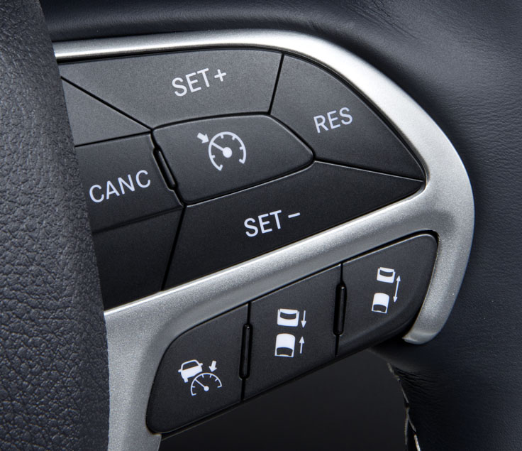
Speed control switches
The speed control switch pod is located in the right spoke of the steering wheel spoke bezel. Two different switches are used. One switch has five buttons and is used on vehicles not equipped with the optional adaptive speed control (also known as the Adaptive Cruise Control/ACC) system. The other switch has eight buttons and is used on vehicles equipped with the ACC system option. These switches are the primary control used by the vehicle operator to manage the particular speed control system installed in the vehicle. The only visible components of the switch pod are the switch push buttons and a decorative bezel around the push buttons, which stands slightly proud of the steering wheel spoke bezel. The remainder of the switch pod including its mounting provisions and its electrical connection are concealed beneath the spoke bezel. The switch pod housing and push buttons are constructed of molded plastic. Each of the push buttons has white International Control and Display Symbol graphics or text applied to it, which clearly identify the function of each push button. The switch pod is secured through three integral mounting tabs to mounting bosses on the back of the spoke bezel by three screws. A connector receptacle integral to the inboard end of the switch pod housing connects the speed control switch and the Local Interface Network (LIN) slave node circuitry integral to the switch pod to the vehicle electrical system through a dedicated take out and connector of the steering wheel wire harness. The speed control switch pod cannot be adjusted or repaired. If any function of the switch or the LIN slave node is ineffective or damaged, the entire switch pod unit must be replaced.
The speed control switch pod is a resistor multiplexed unit that provides LIN bussed inputs to the Steering Control Module (SCM) microprocessor integral to the Steering Column Control Module (SCCM). The speed control switch pod also contains the circuitry of a Local Interface Network (LIN) slave node, which provides source current for and communicates the switch or sensor states of the Electronic Vehicle Information Center (EVIC) switches, the remote radio switches, the paddle shifter switches (if equipped), the horn switch and the heated steering wheel sensor (if equipped) over the LIN data bus to the SCM, which is the LIN master node.
The speed control switch pod for vehicles equipped with a conventional electronic speed control system and not equipped with the optional adaptive speed control (also known as the Adaptive Cruise Control/ACC) system contains four switch push buttons whose functions are:
- On/Off – This switch button enables or disables the speed control system and clears any previous speed control set speed from system memory.
- Resume / + – This switch button restores the vehicle to a previously stored set speed or accelerates the vehicle from an already attained set speed.
- Cancel – This switch button cancels the current speed control event, but does not turn the system OFF or clear the currently stored set speed.
- Set / – – This switch button sets the current vehicle speed as the stored set speed or decelerates (coasts) the vehicle to a speed that is slower than the already attained set speed.
The optional adaptive speed control switch pod for vehicles equipped with the ACC system option contains the same four switch push buttons as the conventional speed control switch pod, then adds two buttons whose functions are:
- Mode – This switch button toggles the speed control system between adaptive (ACC) or conventional (non-ACC) modes of operation.
- Distance Buttons – These switch buttons select the separation or following distance (in seconds) that the ACC system maintains between this vehicle and any preceding vehicle.
The SCM LIN master node provides a clean ground and fused B(+) current for all of the switches and sensors on the rotating steering wheel through the LIN slave node circuitry of the speed control switch pod as well as for the Light Emitting Diode (LED) back lighting of both the speed control and the EVIC switch pods. The SCM continually monitors all of the hard wired speed control switch circuits as well as the LIN bus data. The SCM will set a Diagnostic Trouble Code (DTC) for any problem it detects in the speed control switch circuits, and will store a Signal Not Available (SNA) code for any LIN bus input errors. The SCM also communicates with other electronic modules over the Controller Area Network (CAN) data bus. Therefore, any SCM DTC information can be retrieved using a diagnostic scan tool connected to the Data Link Connector (DLC).
The analog resistor multiplexed circuits of the speed control switch pod as well as the hard wired circuits between the switch pod and the SCM may be diagnosed using conventional diagnostic tools and procedures. Refer to the appropriate wiring information. The wiring information includes wiring diagrams, proper wire and connector repair procedures, details of wire harness routing and retention, connector pin-out information and location views for the various wire harness connectors, splices and grounds.
However, conventional diagnostic methods will not prove conclusive in the diagnosis of the LIN slave or master nodes, the SCM, the SCCM or the electronic controls and communication between modules and other devices that provide some features of the speed control system. The most reliable, efficient, and accurate means to diagnose the speed control switch pod, the LIN slave or master nodes, the SCM or the electronic controls and communication related to speed control system operation requires the use of a diagnostic scan tool. Refer to the appropriate diagnostic information.
–wk2Jeeps.com