Welcome to the JeepSpecs.com In-Depth page on the WK2 Jeep Grand Cherokee adaptive Bi-Xenon headlamps. Did we miss anything? get in touch with us and let us know!

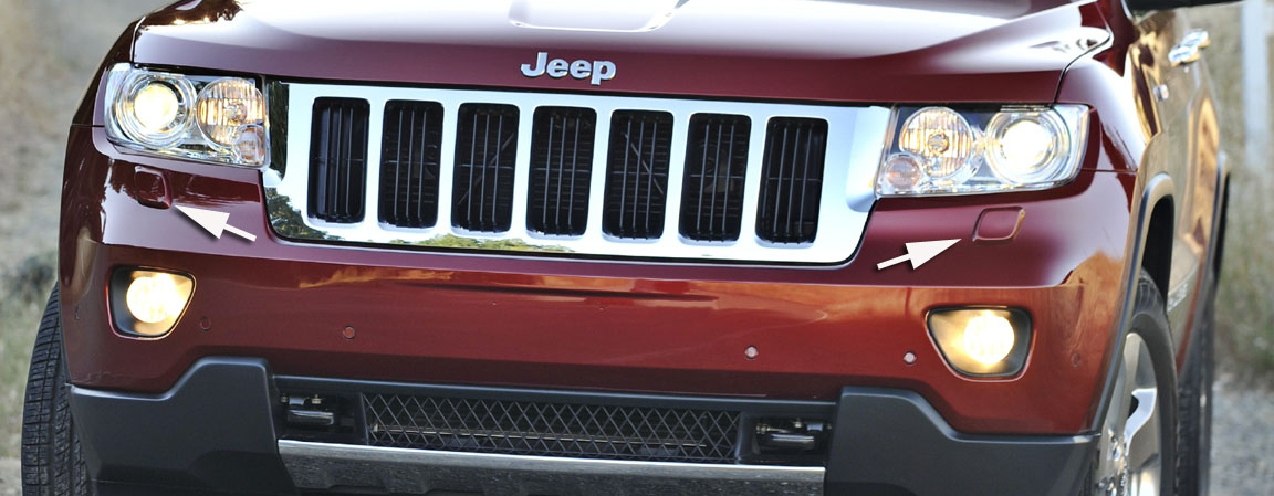
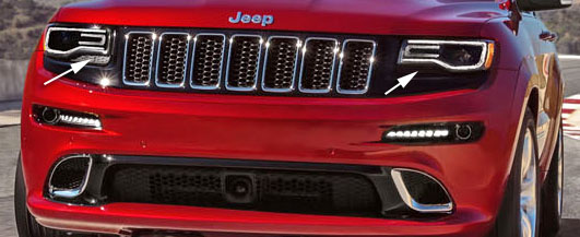
Headlamp washer nozzle housing location (2011-2013 models)

| Availability (North America):
2013 Overland Summit models (Standard) 2014-2020 Summit models (Standard) 2015-2019 Overland High Altitude models (Standard, discontinued during 2019 model year) 2014-2020 SRT models (Standard) 2018-2020 Trackhawk models (Standard) Availability (outside North America): 2011-up selected export models Operation The headlamp washer system is designed to provide the vehicle operator with a convenient, safe, and reliable means of maintaining High Intensity Discharge (HID) headlamp lighting performance. The various components of this system are designed to convert electrical energy produced by the vehicle electrical system into the hydraulic action of the washer system to apply washer fluid stored in an on-board reservoir to the lenses of the two front lamp units, removing excess accumulations of snow, ice, bugs, mud, or other minor debris from the front lamps that might be encountered while driving the vehicle under numerous types of inclement operating conditions. The vehicle operator initiates the headlamp washer system function using the control knob on the end of the multi-function switch control stalk that extends from the left side of the steering column, just below the steering wheel. While the HID headlamps are turned ON, pushing the knob on the end of the control stalk towards the steering column beyond the actuation point for more than about 100 milliseconds (0.10 second) activates the headlamp washer pump/motor in combination with the front washer pump/motor. When the headlamp washer pump/motor unit is energized, hydraulic pressure builds within the headlamp washer system plumbing against the pressure of the return spring in each headlamp washer nozzle. Sufficient pressure causes the headlamp washer nozzles to telescope outward and to dispense high pressure washer fluid onto the lenses of both front lamp units for about 1600 milliseconds (1.6 seconds). Depressing the control knob towards the steering column actuates the momentary front washer system switch, which selects the HEADLAMP WASH mode depending upon when and how long the switch is held closed. Headlamp washer system operation is completely controlled by the Totally Integrated Power Module (TIPM) logic circuits based upon electronic wash command message inputs received from the Steering Control Module (SCM) internal to the Steering Column Control Module (SCCM) for all of the wiper and washer system functions. The SCM then sends electronic wiper switch and washer switch status messages to the TIPM over the Controller Area Network (CAN) data bus requesting the appropriate wiper and washer system operating modes. The TIPM will only allow this system to operate when the ignition switch is in the ON position and the headlamp low beams are turned ON. The TIPM uses a high side driver to energize or de-energize the headlamp washer system relay which, in turn, controls the operation of the headlamp washer pump/motor unit. The hard wired circuits and components of the headlamp washer system may be diagnosed using conventional diagnostic tools and procedures. Refer to the appropriate wiring information. However, conventional diagnostic methods will not prove conclusive in the diagnosis of the headlamp washer system or the electronic controls or communication between other modules and devices that provide some features of the headlamp washer system. The most reliable, efficient, and accurate means to diagnose the headlamp washer system or the electronic controls and communication related to headlamp washer system operation requires the use of a diagnostic scan tool. The headlamp washer system includes the following major components:
Hard wired circuitry connects the headlamp washer system components to the electrical system of the vehicle. These hard wired circuits are integral to several wire harnesses, which are routed throughout the vehicle and retained by many different methods. These circuits may be connected to each other, to the vehicle electrical system and to the headlamp washer system components through the use of a combination of soldered splices, splice block connectors, and many different types of wire harness terminal connectors and insulators. Refer to the appropriate wiring information. The wiring information includes wiring diagrams, proper wire and connector repair procedures, further details on wire harness routing and retention, as well as pin out and location views for the various wire harness connectors, splices and grounds. Plumbing The headlamp washer system plumbing consists of a large diameter high pressure rubber hose that is routed from the outlet nipple of the headlamp washer pump/motor unit on the washer reservoir to one barbed nipple of an elbow fitting near the front upper outboard corner of the reservoir. One end of a hose from the front fascia connects to the other barbed nipple of the elbow fitting on the reservoir, while the other end connects to the barbed nipple of a tee fitting located near the left frame rail on the left side of the front fascia. The other two barbed nipples of the tee fitting are connected to two short lengths of hose that each terminate at a telescopic headlamp washer nozzle behind the fascia and below the two front lamp units. The hose connections at the nozzles, at the washer pump and at the washer reservoir elbow are secured using molded plastic quick-connect fittings. Washer hose or tube is available for service only as roll stock, which must then be cut to length. The molded plastic washer hose fittings cannot be repaired. If these fittings are ineffective or damaged, they must be replaced. Washer pump / motor
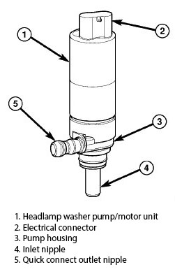
An inlet nipple (4) on the bottom of the pump housing (3) passes through a rubber grommet seal/filter screen installed in a dedicated mounting hole of the washer reservoir. When the pump is installed in the reservoir the quick connect outlet nipple (5) on the pump housing points toward the left side of the vehicle and connects the unit to the headlamp washer plumbing. The headlamp washer pump/motor unit is retained on the reservoir by the interference fit between the pump inlet nipple and the grommet seal, which is a light press fit. The top of the washer pump is also secured to the washer reservoir by a light snap fit into a receptacle molded into the reservoir that allows for mounting of the washer pump without the use of fasteners. An integral connector receptacle (2) on the top of the motor housing connects the unit to the vehicle electrical system through a dedicated take out and connector of the Front End Module (FEM) wire harness. The headlamp washer pump/motor unit cannot be repaired. If ineffective or damaged, the entire headlamp washer pump/ motor unit must be replaced. The rubber grommet seal/filter screen is available for separate service replacement. –wk2Jeeps.com |


